NJM2552V Ver la hoja de datos (PDF) - Japan Radio Corporation
Número de pieza
componentes Descripción
fabricante
NJM2552V Datasheet PDF : 21 Pages
| |||
NJM2552
! Description
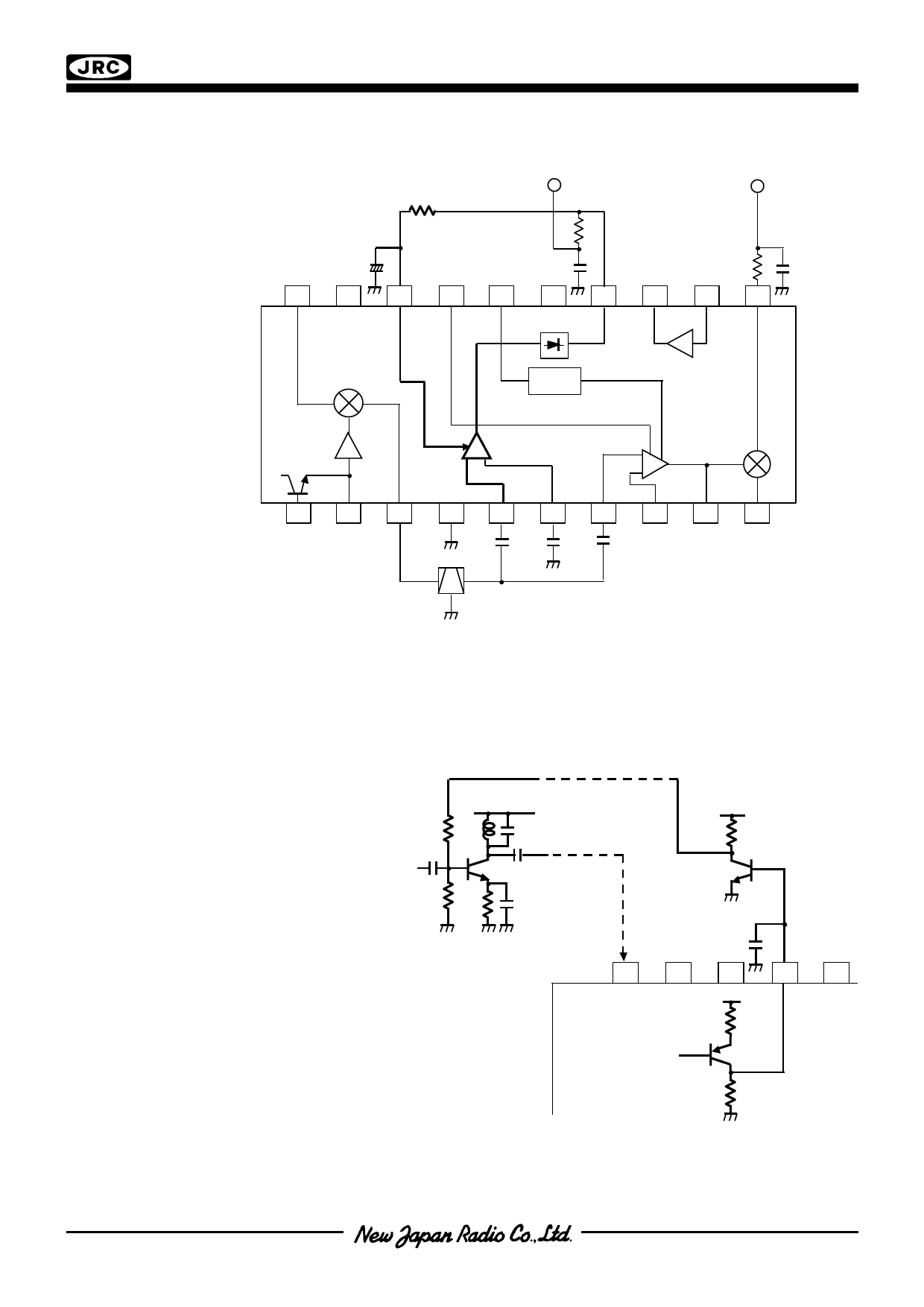
# AM AGC Line
1. Example of external circuit
R3
AM AF
OUT
20k AM AGC Line
C16
10u
+
20
19
18
17
16
15
14
AGC IN
AM
DET
M IXER
RSSI
FM AF
OUT
13
12
11
-A AMP
OSC
AMP
AGC
+
-
AM AMP
AM IF
+ FM AMP
FM
-
DET
1
2
3
4
5
6
7
8
9
10
CERAMIC
FILTER
2. Explanation
AM AGC IN terminal (pin18) is usually connected with the AM DET terminal (pin 14) through the ripple
filter of R3 and C16. This filter has the time constant of R3xC16 and this value of time constant is generally
selected to be 5 to 10 times larger than the lowest cycle of the AM modulation signal (, not AM
demodulated signal). AGC IN terminal (pin 18) can also be controlled by an external DC source instead of
DC output of AM DET terminal.
# RF AGC Line
1. Example of external circuit
RF AGC Line
V++
VV++
RF IN
Tr2
Tr3
RF Amplifier
20
19
MIX IN
from IF Am p
18
V++
2k
17
16
RF AGC
OUT
Tr1
112207kk
2. Explanation
RF AGC OUT terminal (pin17) can be connected to the bias circuit of the external RF amplifier to control
its gain. RF AGC characteristics are shown on following page.
Ver.2007-10-24
- 13 -
Share Link: 