NCP1027P100G(2015) Ver la hoja de datos (PDF) - ON Semiconductor
Número de pieza
componentes Descripción
fabricante
NCP1027P100G
(Rev.:2015)
(Rev.:2015)
ON Semiconductor
NCP1027P100G Datasheet PDF : 30 Pages
| |||
NCP1027
Auto−Recovery Overvoltage Protection
The particular NCP1027 arrangement offers a simple
way to prevent output voltage runaway when the
optocoupler fails. As Figure 34 shows, an active Zener
diode monitors and protects the VCC pin. Below its
equivalent breakdown voltage, that is to say 8.7 V typical,
no current flows in it. If the auxiliary VCC pushes too much
current inside the Zener, then the controller considers an
OVP situation and stops the pulses. Figure 34 shows that
the insertion of a resistor (Rlimit) between the auxiliary DC
level and the VCC pin is mandatory a) not to damage the
internal 8.7 V Zener diode during an overshoot for instance
(absolute maximum current is 15 mA) b) to implement the
fail−safe optocoupler protection (OVP) as offered by the
active clamp. Please note that there cannot be bad
interaction between the clamping voltage of the internal
Zener and VCCON since this clamping voltage is actually
built on top of VCCON with a fixed amount of offset
(200 mV typical). Rlimit should be carefully selected to
avoid triggering the OVP as we discussed, but also to avoid
disturbing the VCC in low/light load conditions. The
following details how to evaluate the Rlimit value.
Self−supplying controllers in extremely low standby
applications often puzzles the designer. Actually, if an
SMPS operated at nominal load can deliver an auxiliary
voltage of an arbitrary 16 V (Vnom), this voltage can drop
below 10 V (Vstby) when entering standby. This is because
the recurrence of the switching pulses expands so much,
that the low frequency refueling rate of the VCC capacitor
is not enough to keep a proper auxiliary voltage. Figure 35
portrays a typical scope shot of an SMPS entering deep
standby (output unloaded). Thus, care must be taken when
calculating Rlimit 1) to not trigger the VCC overcurrent latch
(by injecting 6.0 mA into the active clamp – always use the
minimum value for worse case design) in normal operation
but 2) not to drop too much voltage over Rlimit when
entering standby. Otherwise, the converter will enter burst
mode as it will sense an UVLO condition. Based on these
recommendations, we are able to bound Rlimit between two
equations:
Vnom−Vclamp
Itrip
v
Rlimit
v
Vstby−VCCON
ICC1
(eq. 3)
Where:
Vnom is the auxiliary voltage at nominal load.
Vstdby is the auxiliary voltage when standby is entered.
Itrip is the current corresponding to the nominal operation.
It thus must be selected to avoid false tripping in overshoot
conditions. Always use the minimum of the specification
for a robust design.
ICC1 is the controller consumption. This number slightly
decreases compared to ICC1 from the spec since the part
in standby does almost not switch. It is around 1.0 mA for
the 65 kHz version.
VCC(min) is the level above which the auxiliary voltage
must be maintained to keep the controller away from the
UVLO trip point. It is good to obtain around 8.0 V in order
to offer an adequate design margin, e.g. to not reactivate the
startup source (which is not a problem in itself if low
standby power does not matter).
VCCON = 8.5 V
VCC(min) = 7.5 V
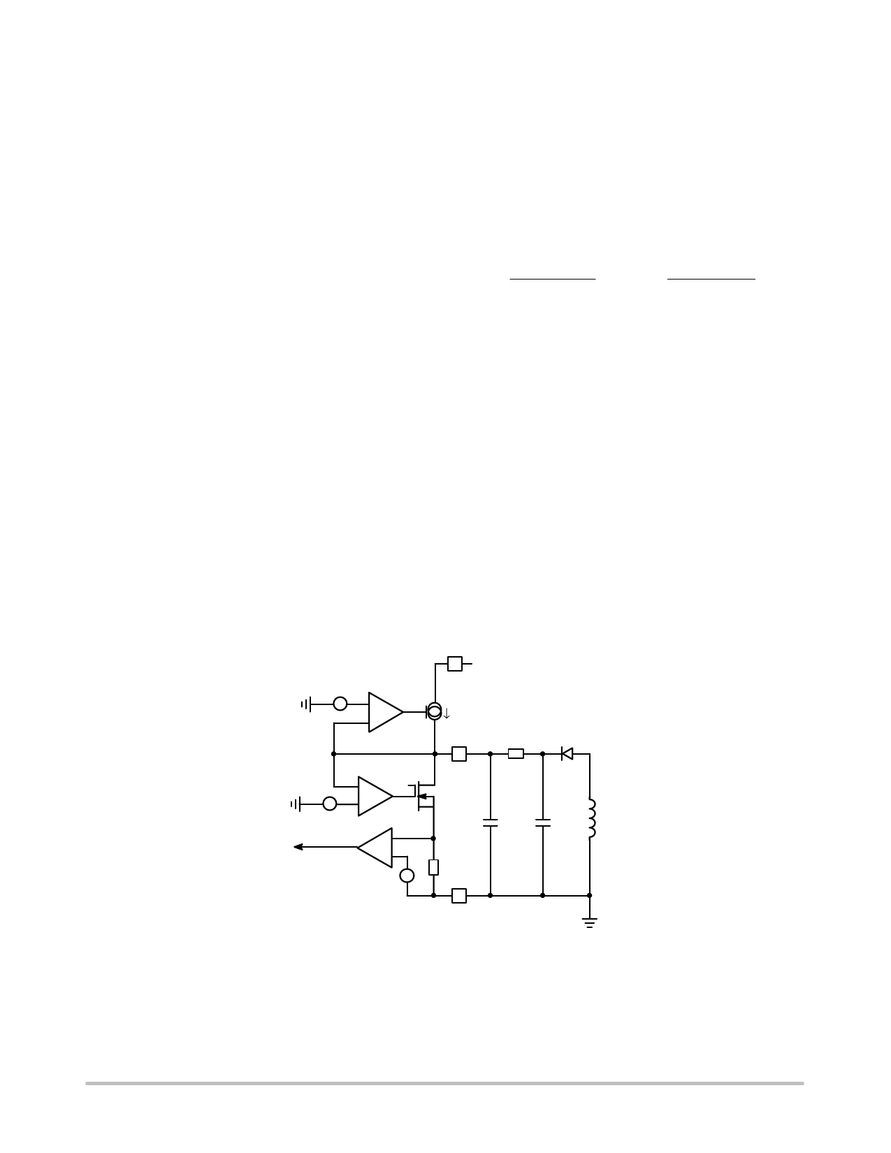
+-
+
Drain
Startup
Source
VCC
Rlimit
D1
+
-
+
Vclamp = 8.7 V Typ.
+
Latch
-
+
+
CVCC
+
CAUX
Laux
I > 6 mA
Ground
Figure 34. A more detailed view of the NCP1027 offers better
insight on how to properly wire an auxiliary winding.
Since Rlimit shall not bother the controller in standby, e.g.
keep Vauxiliary to around 8.0 V (as selected above), we
purposely select a Vnom well above this value. As
explained before, experience shows that a 40% decrease
can be seen on auxiliary windings from nominal operation
down to standby mode. Let’s select a nominal auxiliary
winding of 20 V to offer sufficient margin regarding 8.0 V
when in standby (Rlimit also drops voltage in standby…).
www.onsemi.com
19
Share Link: 