LTC1291BCN8(RevA) Ver la hoja de datos (PDF) - Linear Technology
Número de pieza
componentes Descripción
fabricante
LTC1291BCN8 Datasheet PDF : 20 Pages
| |||
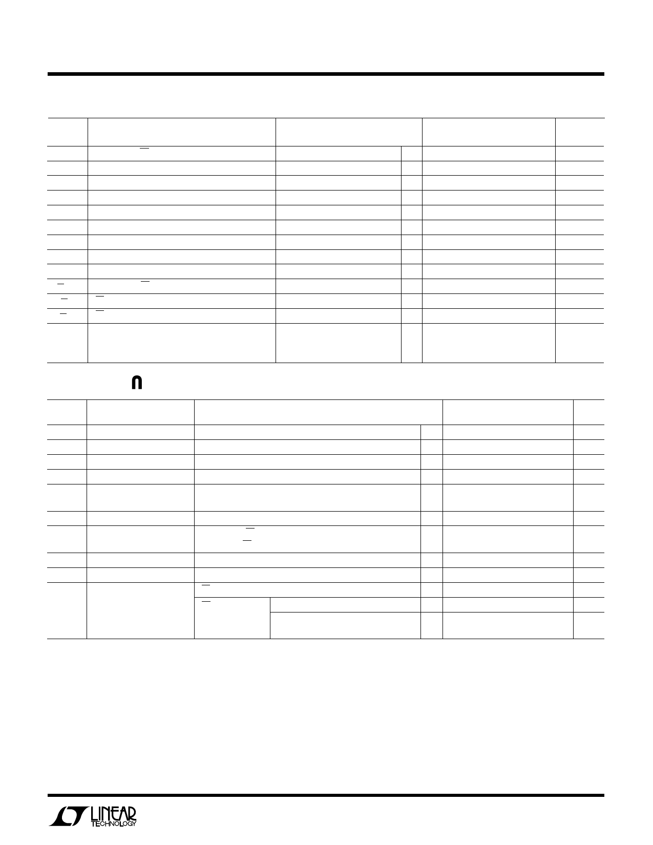
LTC1291
AC CHARACTERISTICS The q denotes the specifications which apply over the full operating temperature range,
otherwise specifications are at TA = 25°C. (Note 3)
SYMBOL PARAMETER
CONDITIONS
LTC1291B/LTC1291C/LTC1291D
MIN TYP MAX
UNITS
tdis
Delay Time, CS↑ to DOUT Hi-Z
See Test Circuits
q
ten
Delay Time, CLK↓ to DOUT Enabled
See Test Circuits
q
thDI
Hold Time, DIN after CLK↑
VCC = 5V (Note 6)
thDO
Time Output Data Remains Valid after CLK↓
tWHCLK
CLK High Time
VCC = 5V (Note 6)
tWLCLK
CLK Low Time
VCC = 5V (Note 6)
tf
DOUT Fall Time
See Test Circuits
q
tr
DOUT Rise Time
See Test Circuits
q
tsuDI
Setup Time, DIN Stable before CLK↑
VCC = 5V (Note 6)
tsuCS
Setup Time, CS↓ before CLK↑
VCC = 5V (Note 6)
tWHCS
CS High Time During Conversion
VCC = 5V (Note 6)
tWLCS
CS Low Time During Data Transfer
VCC = 5V (Note 6)
CIN
Input Capacitance
Analog Inputs On Channel
Analog Inputs Off Channel
Digital Inputs
80 150
80 200
50
130
300
400
65 130
25 50
50
50
500
18
100
5
5
ns
ns
ns
ns
ns
ns
ns
ns
ns
ns
ns
CLK Cycles
pF
pF
pF
DIGITAL A D DC ELECTRICAL CHARACTERISTICS The q denotes the specifications which
apply over the full operating temperature range, otherwise specifications are at TA = 25°C. (Note 3)
SYMBOL PARAMETER
CONDITIONS
LTC1291B/LTC1291C/LTC1291D
MIN TYP MAX
UNITS
VIH
VIL
IIH
IIL
VOH
VOL
IOZ
ISOURCE
ISINK
ICC
High Level Input Voltage
Low Level Input Voltage
High Level Input Current
Low Level Input Current
High Level Output Voltage
Low Level Output Voltage
High Z Output Leakage
Output Source Current
Output Sink Current
Positive Supply Current
VCC = 5.25V
VCC = 4.75V
VIN = VCC
VIN = 0V
VCC = 4.75V, IOUT = –10µA
VCC = 4.75V, IOUT = – 360µA
VCC = 4.75V, IOUT = 1.6mA
VOUT = VCC, CS High
VOUT = 0V, CS High
VOUT = 0V
VOUT = VCC
CS High
CS High Power Shutdown CLK Off
q
2.0
V
q
0.8
V
q
2.5
µA
q
–2.5
µA
4.7
V
q
2.4 4.0
V
q
0.4
V
q
3
µA
q
–3
µA
– 20
mA
20
mA
q
6
12
mA
q
5
10
µA
Note 1: Absolute Maximum Ratings are those values beyond which the life
of a device may be impaired.
Note 2: All voltage values are with respect to ground (unless otherwise
noted).
Note 3: VCC = 5V, CLK = 1.0MHz unless otherwise specified.
Note 4: One LSB is equal to VCC divided by 4096. For example, when VCC =
5V, 1LSB = 5V/4096 = 1.22mV.
Note 5: Linearity error is specified between the actual end points of the
A/D transfer curve. The deviation is measured from the center of the
quantization band.
Note 6: Recommended operating conditions.
Note 7: Two on-chip diodes are tied to each analog input which will
conduct for analog voltages one diode drop below GND or one diode drop
above VCC. Be careful during testing at low VCC levels (4.5V), as high level
analog inputs (5V) can cause this input diode to conduct, especially at
elevated temperature, and cause errors for inputs near full scale. This spec
allows 50mV forward bias of either diode. This means that as long as the
analog input does not exceed the supply voltage by more than 50mV, the
output code will be correct.
Note 8: Channel leakage current is measured after the channel selection.
Note 9: Increased leakage currents at elevated temperatures cause the
S/H to droop, therefore it is recommended that fCLK ≥ 125kHz at 125°C,
fCLK ≥ 30kHz at 85°C and fCLK ≥ 3kHz at 25°C.
1291fa
3
Share Link: 