IRG4BC30KD-SPBF(2004) Ver la hoja de datos (PDF) - International Rectifier
Número de pieza
componentes Descripción
fabricante
IRG4BC30KD-SPBF
(Rev.:2004)
(Rev.:2004)
International Rectifier
IRG4BC30KD-SPBF Datasheet PDF : 10 Pages
| |||
IRG4BC30KD-SPbF
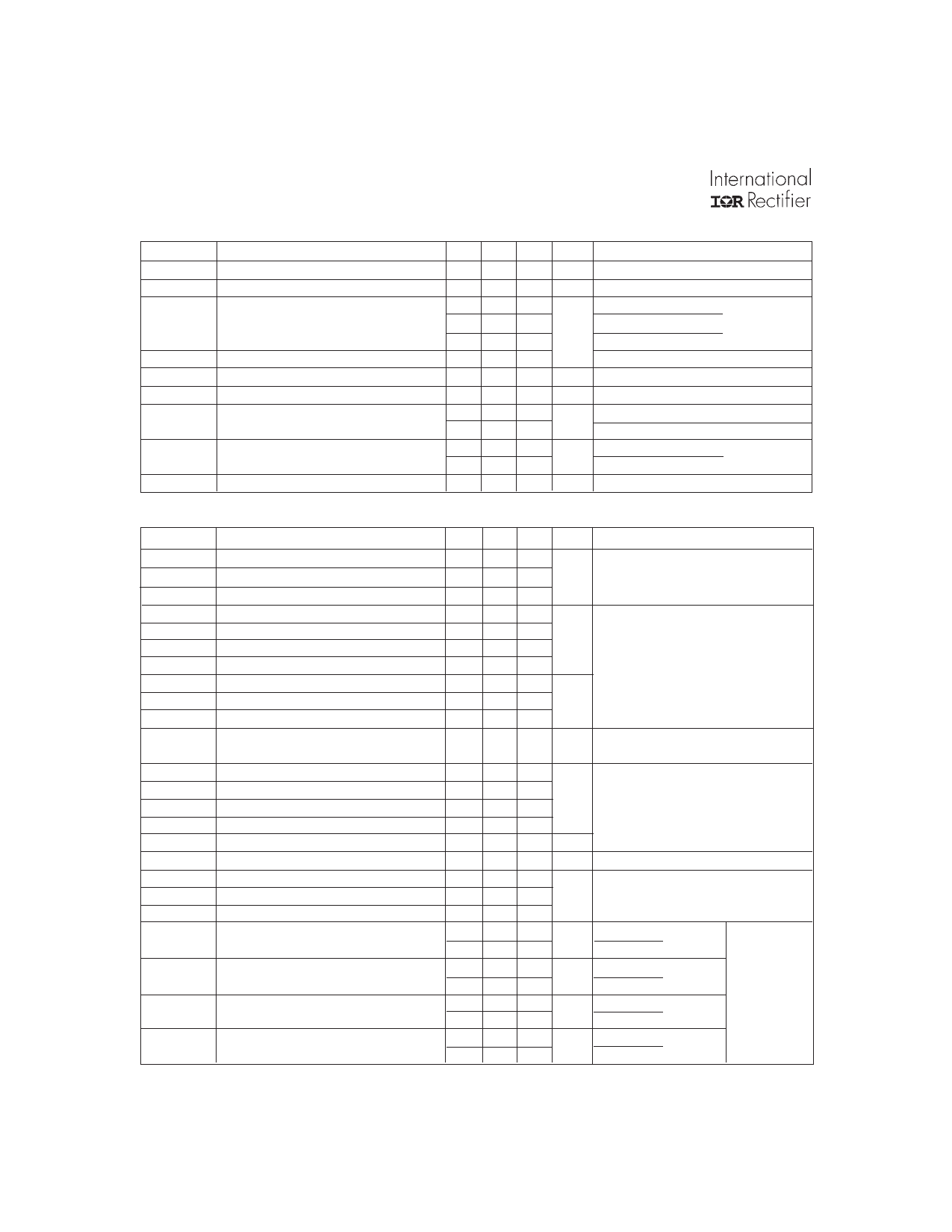
Electrical Characteristics @ TJ = 25°C (unless otherwise specified)
Parameter
Min. Typ. Max. Units
Conditions
V(BR)CES Collector-to-Emitter Breakdown Voltage
∆V(BR)CES/∆TJ Temperature Coeff. of Breakdown Voltage
VCE(on)
Collector-to-Emitter Saturation Voltage
VGE(th)
∆VGE(th)/∆TJ
gfe
ICES
Gate Threshold Voltage
Temperature Coeff. of Threshold Voltage
Forward Transconductance
Zero Gate Voltage Collector Current
VFM
Diode Forward Voltage Drop
IGES
Gate-to-Emitter Leakage Current
600 V VGE = 0V, IC = 250µA
0.54 V/°C VGE = 0V, IC = 1.0mA
2.21 2.7
IC = 16A
VGE = 15V
2.88
2.36
IC = 28A
See Fig. 2, 5
V IC = 16A, TJ = 150°C
3.0 6.0
VCE = VGE, IC = 250µA
-12 mV/°C VCE = VGE, IC = 250µA
5.4 8.1 S VCE = 100V, IC = 16A
250 µA VGE = 0V, VCE = 600V
2500
VGE = 0V, VCE = 600V, TJ = 150°C
1.4 1.7
1.3 1.6
V IC = 12A
See Fig. 13
IC = 12A, TJ = 150°C
±100 nA VGE = ±20V
Switching Characteristics @ TJ = 25°C (unless otherwise specified)
Qg
Qge
Qgc
td(on)
tr
td(off)
tf
Eon
Eoff
Ets
tsc
td(on)
tr
td(off)
tf
Ets
LE
Cies
Coes
Cres
trr
Irr
Qrr
di(rec)M/dt
Parameter
Total Gate Charge (turn-on)
Gate - Emitter Charge (turn-on)
Gate - Collector Charge (turn-on)
Turn-On Delay Time
Rise Time
Turn-Off Delay Time
Fall Time
Turn-On Switching Loss
Turn-Off Switching Loss
Total Switching Loss
Short Circuit Withstand Time
Turn-On Delay Time
Rise Time
Turn-Off Delay Time
Fall Time
Total Switching Loss
Internal Emitter Inductance
Input Capacitance
Output Capacitance
Reverse Transfer Capacitance
Diode Reverse Recovery Time
Diode Peak Reverse Recovery Current
Diode Reverse Recovery Charge
Diode Peak Rate of Fall of Recovery
During tb
Min.
10
Typ.
67
11
25
60
42
160
80
0.60
0.58
1.18
58
42
210
160
1.69
7.5
920
110
27
42
80
3.5
5.6
80
220
180
160
Max.
100
16
37
250
120
1.6
60
120
6.0
10
180
600
Units
nC
ns
mJ
µs
ns
mJ
nH
pF
ns
A
nC
A/µs
Conditions
IC = 16A
VCC = 400V
See Fig.8
VGE = 15V
TJ = 25°C
IC = 16A, VCC = 480V
VGE = 15V, RG = 23Ω
Energy losses include "tail"
and diode reverse recovery
See Fig. 9,10,14
VCC = 360V, TJ = 125°C
VGE = 15V, RG = 10Ω , VCPK < 500V
TJ = 150°C,
See Fig. 11,14
IC = 16A, VCC = 480V
VGE = 15V, RG = 23Ω
Energy losses include "tail"
and diode reverse recovery
Measured 5mm from package
VGE = 0V
VCC = 30V
= 1.0MHz
See Fig. 7
TJ = 25°C See Fig.
TJ = 125°C 14
IF = 12A
TJ = 25°C See Fig.
TJ = 125°C 15
VR = 200V
TJ = 25°C See Fig.
TJ = 125°C
16 di/dt = 200Aµs
TJ = 25°C See Fig.
TJ = 125°C 17
2
www.irf.com
Share Link: 