IN74HCT125AN Ver la hoja de datos (PDF) - Integral Corp.
Número de pieza
componentes Descripción
fabricante
IN74HCT125AN Datasheet PDF : 5 Pages
| |||
IN74HCT125A
AC ELECTRICAL CHARACTERISTICS(VCC=5.0 V ± 10%, CL=50pF,Input tr=tf=6.0 ns)
Guaranteed Limit
Symbol
Parameter
25 °C ≤85°C ≤125 Unit
to
°C
-55°C
tPLH, Maximum Propagation Delay, Input A to 18
23
27 ns
tPHL Output Y (Figures 1 and 3)
tPLZ, Maximum Propagation Delay, Output 24
30
36 ns
tPHZ Enable toY (Figures 2 and 4)
tPZL, Maximum Propagation Delay, Output 18
23
27 ns
tPZH Enable toY (Figures 2 and 4)
tTLH, tTHL Maximum Output Transition Time, Any 12
15
18 ns
Output
(Figures 1 and 3)
CIN Maximum Input Capacitance
10
10
10 pF
COUT Maximum
Three-State
Output 15
15
15 pF
Capacitance (Output in High-Impedance
State)
Power Dissipation Capacitance (Per Typical @25°C,VCC=5.0
Buffer)
V
CPD Used to determine the no-load dynamic
48
pF
power
consumption:
PD=CPDVCC2f+ICCVCC
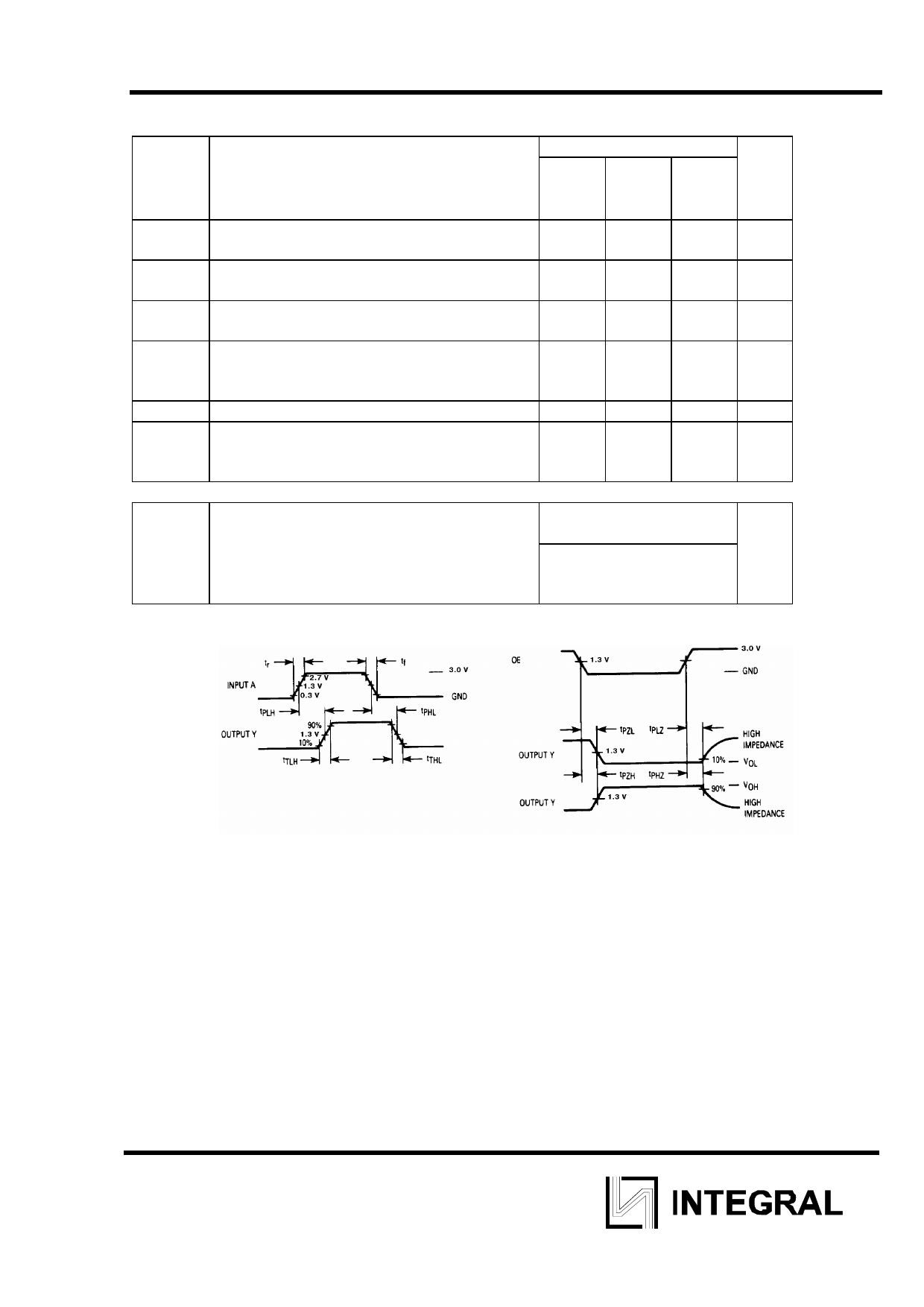
Figure 1. Switching Waveforms
Figure 2. Switching Waveforms
4
Share Link: 