AD7715 Ver la hoja de datos (PDF) - Analog Devices
Número de pieza
componentes Descripción
fabricante
AD7715 Datasheet PDF : 40 Pages
| |||
AD7715
TEMPERATURE MEASUREMENT
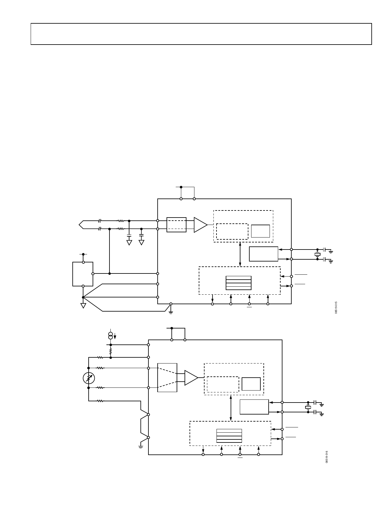
Another application area for the AD7715 is in temperature
measurement. Figure 15 outlines a connection from a thermo-
couple to the AD7715. In this application, the AD7715 is operated
in its buffered mode to allow large decoupling capacitors on the
front end to eliminate any noise pickup that there may have
been in the thermocouple leads. When the AD7715 is operated
in buffered mode, it has a reduced common-mode range. To place
the differential voltage from the thermocouple on a suitable
common-mode voltage, the AIN(−) input of the AD7715 is
biased up at the reference voltage, 2.5 V.
Figure 16 shows another temperature measurement application
for the AD7715. In this case, the transducer is an resistive tem-
perature device (RTD), a PT100. The arrangement is a 4-lead
RTD configuration. There are voltage drops across the lead
resistances RL1 and RL4, but these simply shift the common-
mode voltage. There is no voltage drop across lead resistances
RL2 and RL3 as the input current to the AD7715 is very low. The
lead resistances present a small source impedance so it would
not generally be necessary to turn on the buffer on the AD7715.
If the buffer is required, the common-mode voltage should be
set accordingly by inserting a small resistance between the bottom
end of the RTD and AGND of the AD7715. In the application
shown in Figure 16, an external 400 μA current source provides
the excitation current for the PT100 and it also generates the
reference voltage for the AD7715 via the 6.25 kΩ resistor. Varia-
tions in the excitation current do not affect the circuit as both the
input voltage and the reference voltage vary ratiometrically with
the excitation current. However, the 6.25 kΩ resistor must have
a low temperature coefficient to avoid errors in the reference
voltage over temperature.
THERMOCOUPLE
JUNCTION
+5V
+VIN
REF192 VOUT
GND
R
AIN(+)
R
AIN(–)
CC
5V
AVDD
DVDD
AD7715
CHARGE BALANCING ADC
BUFFER
PGA
A = 1 TO 128
AUTO-ZEROED DIGITAL
Σ-∆
MODULATOR
FILTER
REF IN(+)
REF IN(–)
AGND
SERIAL INTERFACE
CLOCK
GENERATION
REGISTER BANK
MCLK IN
MCLK OUT
RESET
DRDY
DGND
DOUT DIN
CS
SCLK
Figure 15. Thermocouple Measurement Using the AD7715
+5V
400µA
REF IN(+)
AVDD
DVDD
RL1
6.25kΩ
REF IN(–)
AD7715
RL2
AIN(+)
CHARGE BALANCING ADC
RTD
RL3
RL4
AIN(–)
BUFFER
PGA
A = 1 TO 128
AUTO-ZEROED DIGITAL
Σ-∆
MODULATOR
FILTER
AGND
DGND
CLOCK
GENERATION
SERIAL INTERFACE
REGISTER BANK
MCLK IN
MCLK OUT
RESET
DRDY
DOUT DIN
CS
SCLK
Figure 16. RTD Measurement Using the AD7715
Rev. D | Page 37 of 40
Share Link: 