BB814-1(2009) Ver la hoja de datos (PDF) - Vishay Semiconductors
Número de pieza
componentes Descripción
fabricante
BB814-1 Datasheet PDF : 3 Pages
| |||
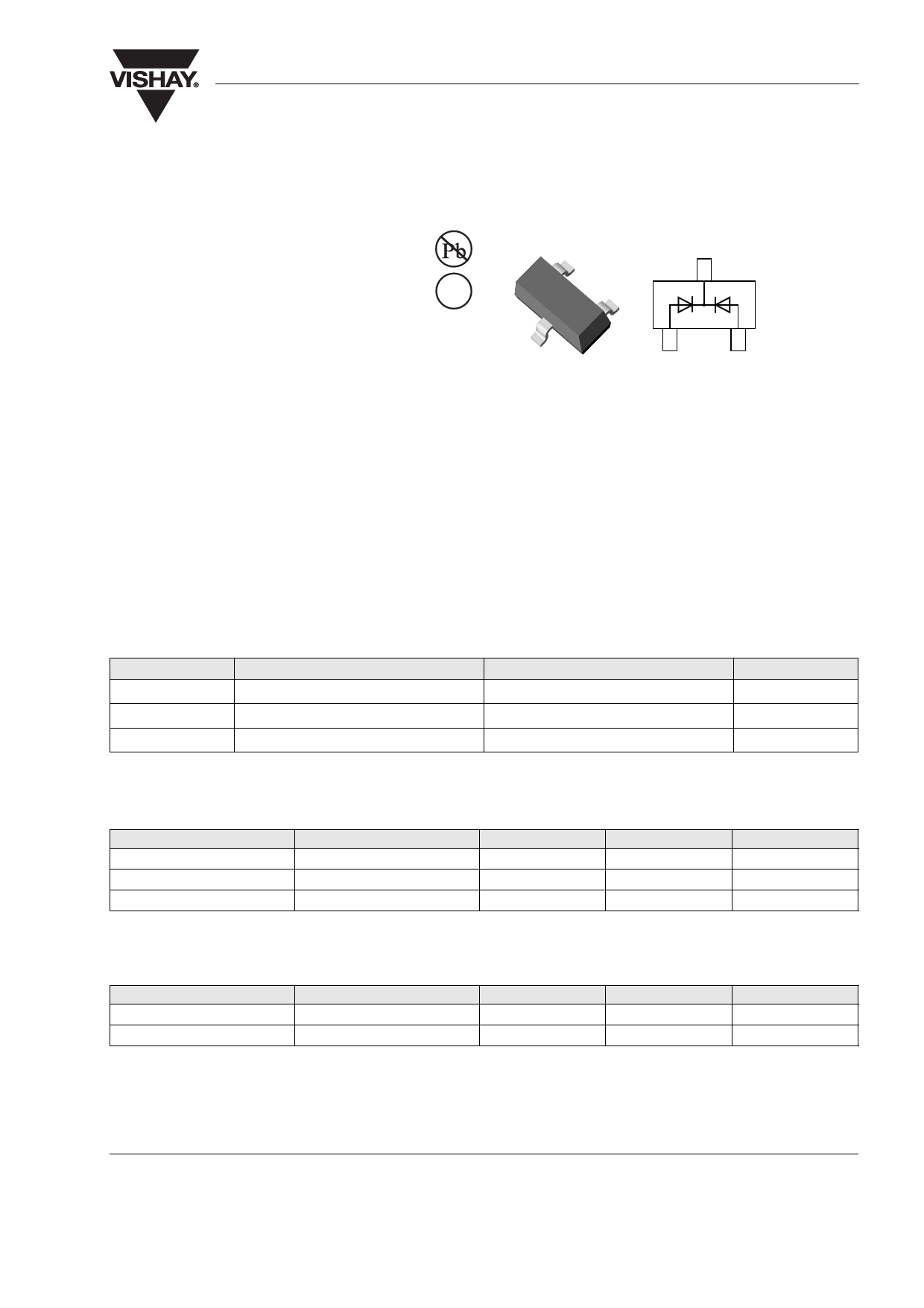
Dual Varicap Diode
BB814
Vishay Semiconductors
3
1
2
18108
MECHANICAL DATA
Case: SOT23
Weight: approx. 8.1 mg
Packaging codes/options:
GS18/10K per 13" reel (8 mm tape), 10K/box
GS08/3K per 7" reel (8 mm tape), 15K/box
FEATURES
• Silicon epitaxial planar diode
• Common cathode
• AEC-Q101 qualified
• Compliant to RoHS directive 2002/95/EC and
in accordance to WEEE 2002/96/EC
APPLICATIONS
• Tuning of separate resonant circuits
• Push-pull circuits in FM range
• Especially for car radios
PARTS TABLE
PART
BB814-1
BB814-2
TYPE DIFFERENTIATION
VRRM = 20 V, CD2 = 43 pF to 45.5 pF
VRRM = 20 V, CD2 = 44.5 pF to 46.5 pF
ORDERING CODE
BB814-1-GS18 or BB814-1-GS08
BB814-2-GS18 or BB814-2-GS08
TYPE MARKING
SH1
SH2
REMARKS
Tape and reel
Tape and reel
ABSOLUTE MAXIMUM RATINGS (1)
PARAMETER
TEST CONDITIONS
Repetitive peak reverse voltage
Reverse voltage
Forward current
Note
(1) Tamb = 25 °C, unless otherwise specified
SYMBOL
VRRM
VR
IF
VALUE
20
18
50
THERMAL CHARACTERISTICS (1)
PARAMETER
TEST CONDITIONS
Junction temperature
Storage temperature range
Note
(1) Tamb = 25 °C, unless otherwise specified
SYMBOL
Tj
Tstg
VALUE
125
- 55 to + 150
ELECTRICAL CHARACTERISTICS (1)
PARAMETER
TEST CONDITIONS
PART SYMBOL MIN.
TYP.
Reverse current
Diode capacitance (2)
Capacitance ratio
Series resistance
VR = 16 V
VR = 16 V, Tj = 60 °C
VR = 2 V
VR = 8 V
VR = 2 V, 8 V, f = 1 MHz
CD = 38 pF, f = 100 MHz
BB814-1
BB814-2
BB814-1
BB814-2
IR
IR
CD2
CD2
CD8
CD8
CD2/CD8
Rs
43
44.5
19.1
19.75
2.05
Notes
(1) Tamb = 25 °C, unless otherwise specified
(2) In the reverse voltage range of VR = (2 V to 8 V) for diodes 4 taped in sequence the max. deviation is 3 %
UNIT
V
V
mA
UNIT
°C
°C
MAX.
20
200
45.5
46.5
21.95
22.70
2.25
0.5
UNIT
nA
nA
pF
pF
pF
pF
Ω
Document Number: 85555
Rev. 1.9, 19-Nov-09
For technical questions, contact: DiodesSSP@vishay.com
www.vishay.com
1
Share Link: 