AOZ1019AI Ver la hoja de datos (PDF) - Alpha and Omega Semiconductor
Número de pieza
componentes Descripción
fabricante
AOZ1019AI Datasheet PDF : 14 Pages
| |||
AOZ1019
Ordering Information
Part Number
Ambient Temperature Range
AOZ1019AI
-40°C to +85°C
Package
SO-8
Environmental
RoHS
Pin Configuration
NC 1
VIN 2
AGND 3
FB 4
8 PGND
7 LX
6 EN
5 COMP
SO-8
(Top View)
Pin Description
Pin Number Pin Name
Pin Function
1
NC
Not connected.
2
VIN
Supply voltage input. When VIN rises above the UVLO threshold the device starts up.
3
AGND Reference connection for controller section. Also used as thermal connection for controller
section. Electrically needs to be connected to PGND.
4
FB
The FB pin is used to determine the output voltage via a resistor divider between the output and GND.
5
COMP External loop compensation pin.
6
EN
The enable pin is active high. Connect EN pin to VIN if not used. Do not leave the EN pin floating.
7
LX
PWM output connection to inductor. Thermal connection for output stage.
8
PGND Power ground. Electrically needs to be connected to AGND.
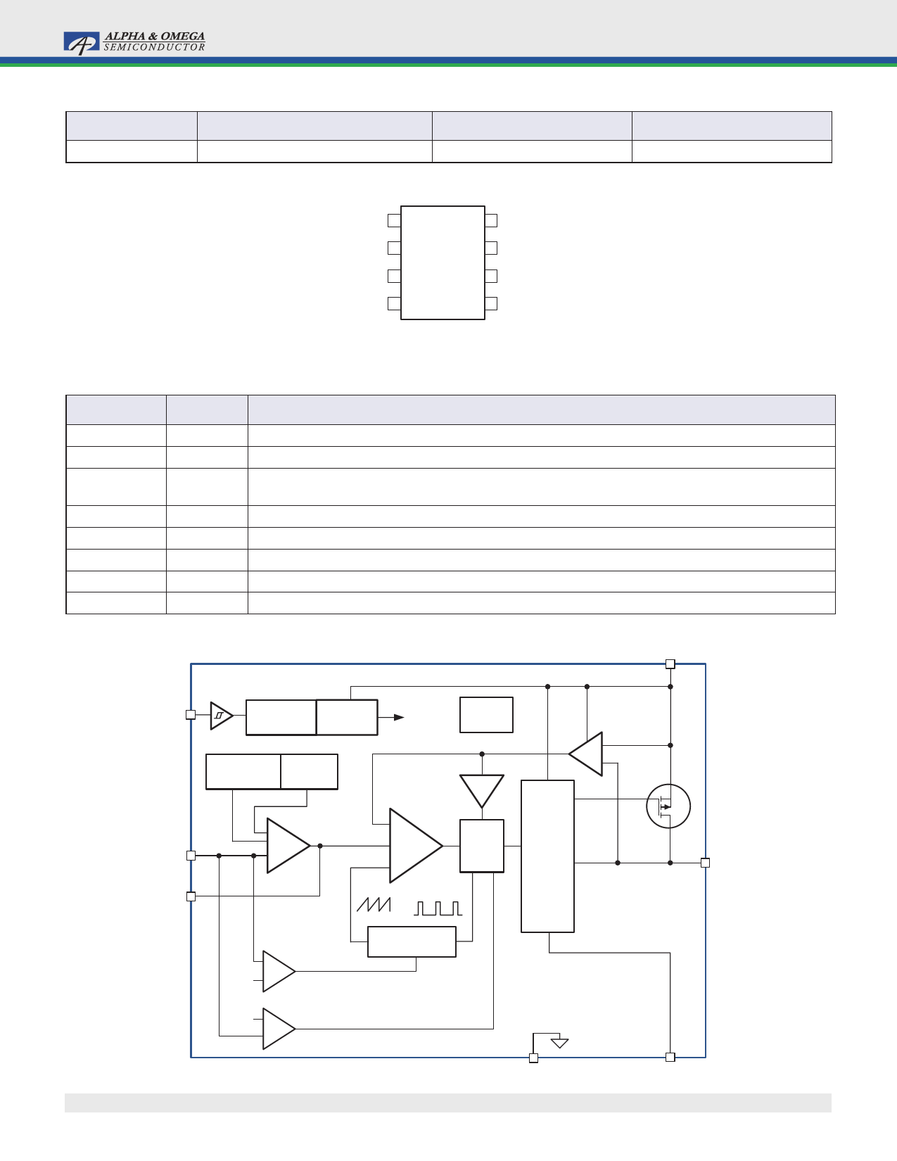
Block Diagram
VIN
EN
UVLO
5V LDO
Internal
OTP
& POR
Regulator
+5V
Reference
& Bias
Softstart
ILimit
+
ISen
–
0.8V
FB
COMP
+
EAmp
–
+
– PWM
Comp
+
PWM
Control
Logic
Level
Shifter
+
FET
Driver
0.2V
0.96V
Frequency
Foldback
+ Comparator
–
Over Voltage
Protection
+ Comparator
–
Rev. 1.0 September 2007
500kHz/63kHz
Oscillator
AGND
www.aosmd.com
Q1
LX
PGND
Page 2 of 14
Share Link: 