AN7293NFBQ View Datasheet(PDF) - Panasonic Corporation
Part Name
Description
MFG CO.
AN7293NFBQ Datasheet PDF : 7 Pages
| |||
AN7293NFBQ
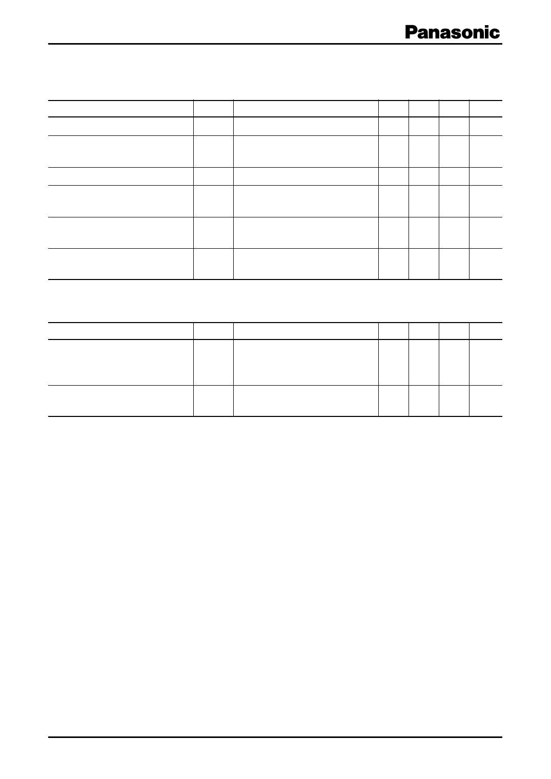
I Electrical Characteristics at Ta = 25°C (continued)
Unless otherwise specified, VCC = 8V, VIN1 is f = 10.70 MHz, Mod. = 1 kHz, 30%
FM modulation stereo input is L + R = 90% VP = 10%
Parameter
Symbol
Conditions
Min Typ Max Unit
SD sensitivity
SD bandwidth
Supply current
Limiting sensitivity
SDS
SDW
ITOT
VLIM
VIN1 when V20 = 2 V, V19 > 2 V
VIN bandwidth when V24 = 2 V,
and V19 > 2 V, VIN1 = 100 dBµ
Without input
VIN1 input level when pin 5 AC
voltage drops by 3 dB
70 80 90 dBµ
100 130 160 kHz
30 37 44 mA
24 32 38 dBµ
ATC
Gate pulse width
VATC L-ch. output ratio when
V2 = 2 V and 0 V
7 11 15 dB
PW VIN2 = (pulse width 1 µs, 0.3 V[p-p] 16 23 30 µs
1 kHz) pin 18 output pulse width
• Design reference data
Note) The following characteristics are the reference values for design and not guaranteed values.
Parameter
Symbol
Conditions
Min Typ Max Unit
Stereo lamp turn off level
AFC offset voltage
LAMPOFF Ratio between the modulation factor 2.0 6.0 10.0 dB
when pin 19 becomes 2 V or more
and LAMPON
VAFC Without signal input, DC potential − 0.1 0.0 0.1 V
difference between pin 21 and pin 26.
4
SDC00007BEB
Share Link: 