M48T02 View Datasheet(PDF) - STMicroelectronics
Part Name
Description
MFG CO.
M48T02 Datasheet PDF : 19 Pages
| |||
M48T02, M48T12
CLOCK OPERATIONS
Reading the Clock
Updates to the TIMEKEEPER® registers should
be halted before clock data is read to prevent
reading data in transition. The BiPORT™ TIME-
KEEPER cells in the RAM array are only data reg-
isters and not the actual clock counters, so
updating the registers can be halted without dis-
turbing the clock itself.
Updating is halted when a '1' is written to the
READ Bit, the seventh bit in the control register.
As long as a '1' remains in that position, updating
is halted. After a halt is issued, the registers reflect
the count; that is, the day, date, and the time that
were current at the moment the halt command was
issued.
All of the TIMEKEEPER registers are updated si-
multaneously. A halt will not interrupt an update in
progress. Updating is within a second after the bit
is reset to a '0.'
Setting the Clock
The eighth bit of the control register is the WRITE
Bit. Setting the WRITE Bit to a '1,' like the READ
Bit, halts updates to the TIMEKEEPER registers.
The user can then load them with the correct day,
date, and time data in 24 hour BCD format (on Ta-
ble 11). Resetting the WRITE Bit to a '0' then trans-
fers the values of all time registers (7F9-7FF) to
the actual TIMEKEEPER counters and allows nor-
mal operation to resume. The FT Bit and the bits
marked as '0' in Table 11 must be written to '0' to
allow for normal TIMEKEEPER and RAM opera-
tion.
See the Application Note AN923, “TIMEKEEPER®
Rolling Into the 21st Century” for information on
Century Rollover.
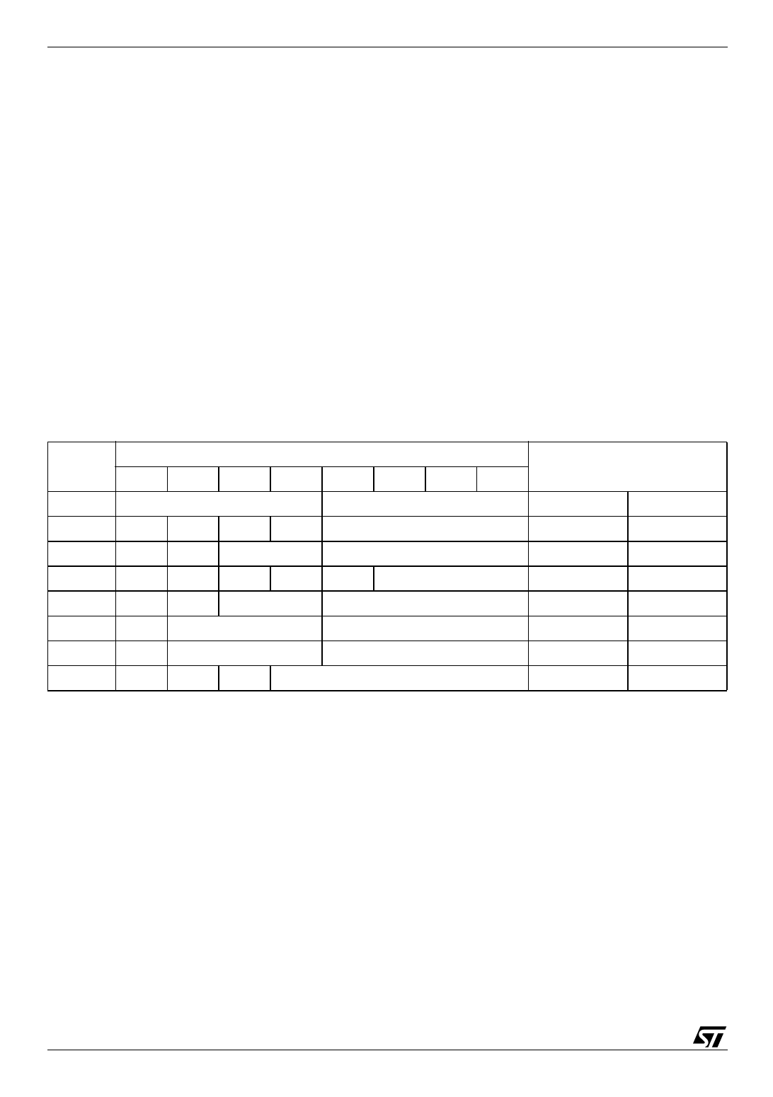
Table 11. Register Map
Data
Address
D7
D6
D5
D4
D3
D2
D1
D0
7FF
10 Years
Year
7FE
0
0
0
10 M
Month
7FD
0
0
10 Date
Date
7FC
0
FT
0
0
0
Day
7FB
0
0
10 Hours
Hours
7FA
0
10 Minutes
Minutes
7F9
ST
10 Seconds
Seconds
7F8
W
R
S
Calibration
Keys: S = SIGN Bit
FT = FREQUENCY TEST Bit (Set to '0' for normal clock operation)
R = READ Bit
W = WRITE Bit
ST = STOP Bit
0 = Must be set to '0'
Function/Range
BCD Format
Year
Month
Date
Day
Hours
Minutes
Seconds
Control
00-99
01-12
01-31
01-07
00-23
00-59
00-59
12/19
Share Link: 