74HC2G14-Q100 View Datasheet(PDF) - NXP Semiconductors.
Part Name
Description
MFG CO.
74HC2G14-Q100 Datasheet PDF : 21 Pages
| |||
Nexperia
74HC2G14-Q100; 74HCT2G14-Q100
Dual inverting Schmitt trigger
9,
W:
QHJDWLYH
SXOVH
90
9
WI
9,
SRVLWLYH
SXOVH
WU
90
9
W:
90
WU
WI
90
9,
*
9&&
92
'87
57
9&&
5/ 6
&/
RSHQ
DDG
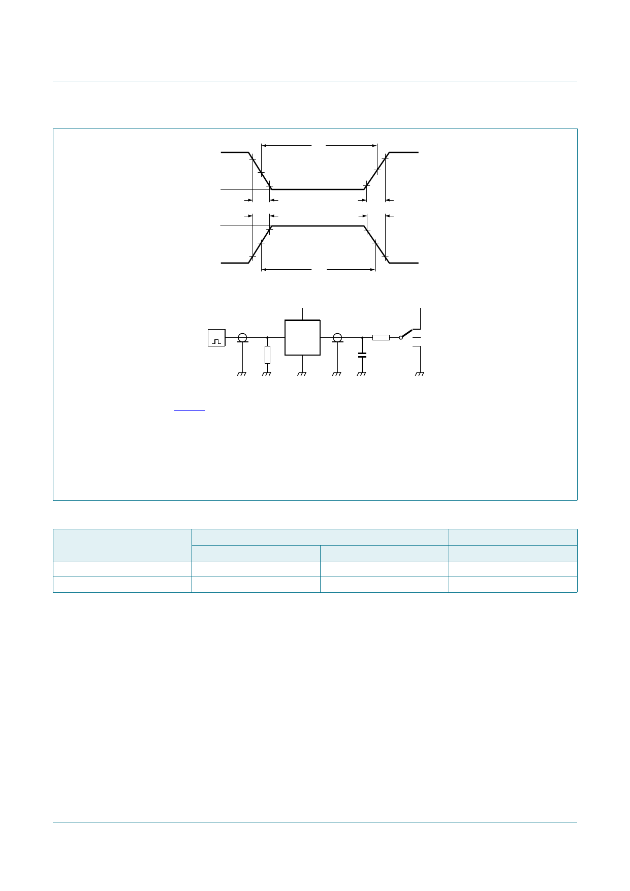
Fig 6.
Test data is given in Table 11.
Definitions test circuit:
RT = Termination resistance should be equal to output impedance Zo of the pulse generator.
CL = Load capacitance including jig and probe capacitance.
RL = Load resistance.
S1 = Test selection switch.
Test circuit for measuring switching times
Table 11. Test data
Type
Input
VI
tr, tf
74HC2G14-Q100
GND to VCC
6 ns
74HCT2G14-Q100
GND to 3.0 V
6 ns
Test
tPHL, tPLH
open
open
74HC_HCT2G14_Q100
Product data sheet
All information provided in this document is subject to legal disclaimers.
Rev. 1 — 20 March 2014
© Nexperia B.V. 2017. All rights reserved
9 of 21
Share Link: 