AD5737 View Datasheet(PDF) - Analog Devices
Part Name
Description
MFG CO.
AD5737 Datasheet PDF : 44 Pages
| |||
Data Sheet
ABSOLUTE MAXIMUM RATINGS
TA = 25°C, unless otherwise noted. Transient currents of up to
100 mA do not cause SCR latch-up.
Table 4.
Parameter
AVDD, VBOOST_x to AGND, DGND
AVCC to AGND
DVDD to DGND
Digital Inputs to DGND
Digital Outputs to DGND
REFIN, REFOUT to AGND
IOUT_x to AGND
SWx to AGND
AGND, GNDSWx to DGND
Operating Temperature Range (TA)
Industrial1
Storage Temperature Range
Junction Temperature (TJ max)
Power Dissipation
Lead Temperature
Soldering
Rating
−0.3 V to +33 V
−0.3 V to +7 V
−0.3 V to +7 V
−0.3 V to DVDD + 0.3 V or +7 V
(whichever is less)
−0.3 V to DVDD + 0.3 V or +7 V
(whichever is less)
−0.3 V to AVDD + 0.3 V or +7 V
(whichever is less)
AGND to VBOOST_x or 33 V if
using the dc-to-dc converter
−0.3 V to +33 V
−0.3 V to +0.3 V
−40°C to +105°C
−65°C to +150°C
125°C
(TJ max − TA)/θJA
JEDEC industry standard
J-STD-020
1 Power dissipated on chip must be derated to keep the junction temperature
below 125°C.
AD5737
Stresses above those listed under Absolute Maximum Ratings
may cause permanent damage to the device. This is a stress
rating only; functional operation of the device at these or any
other conditions above those indicated in the operational
section of this specification is not implied. Exposure to absolute
maximum rating conditions for extended periods may affect
device reliability.
THERMAL RESISTANCE
Junction-to-air thermal resistance (θJA) is specified for a JEDEC
4-layer test board.
Table 5. Thermal Resistance
Package Type
θJA
64-Lead LFCSP (CP-64-3)
20
Unit
°C/W
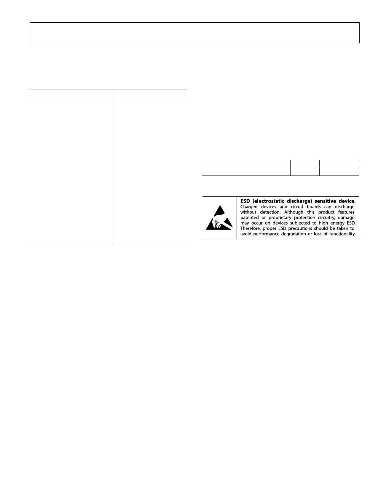
ESD CAUTION
Rev. B | Page 9 of 44
Share Link: 