74HC191DB,118 View Datasheet(PDF) - NXP Semiconductors.
Part Name
Description
MFG CO.
74HC191DB,118 Datasheet PDF : 19 Pages
| |||
Nexperia
74HC191
Presettable synchronous 4-bit binary up/down counter
Vl
Dn input
VM
GND
Vl
tsu
th
tsu
th
PL input
VM
GND
aaa-024390
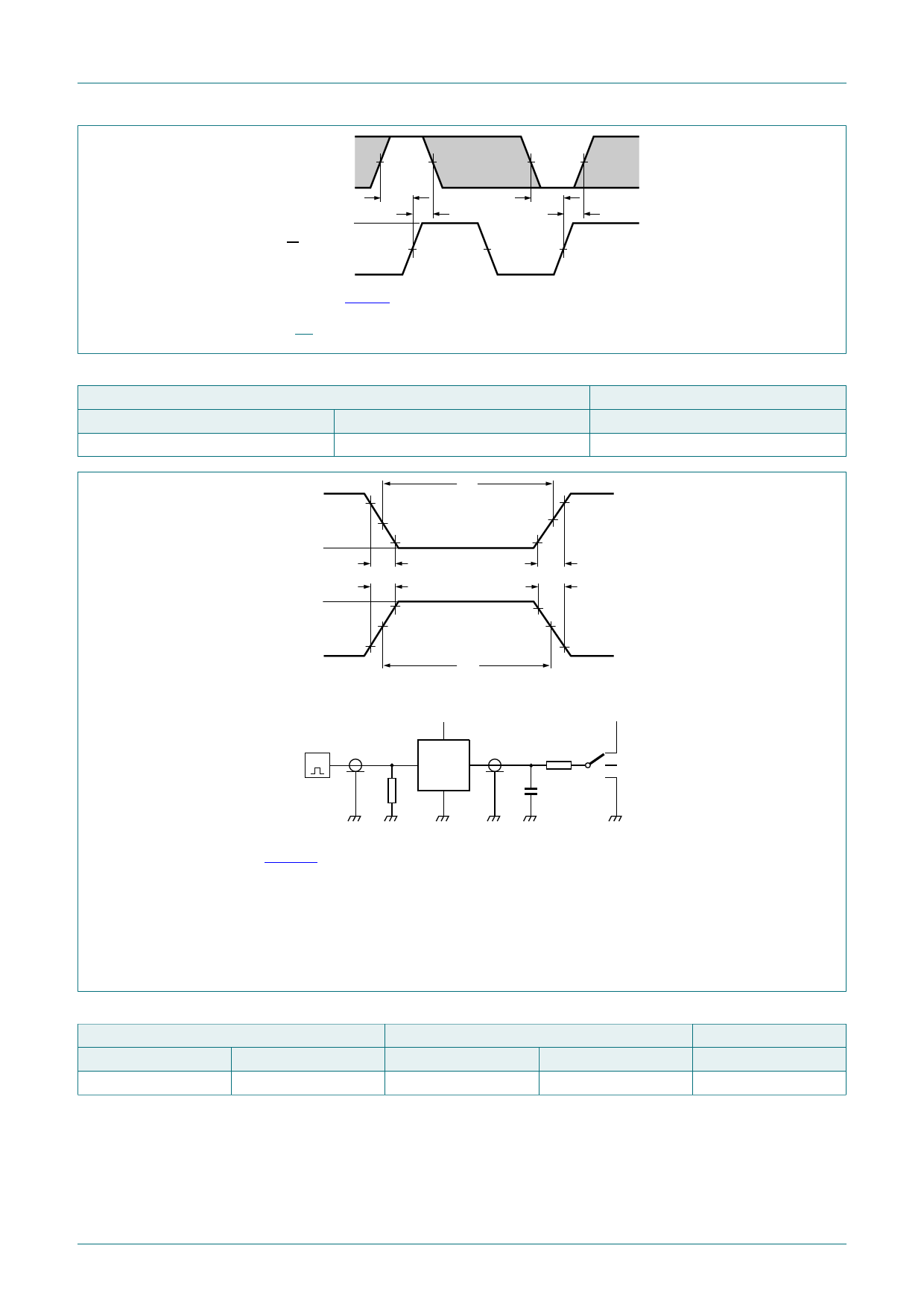
Measurement points are given in Table 9.
The shaded areas indicate when the input is permitted to change for predictable output performance.
Fig. 17. The parallel load input (PL) to data input (Dn) set-up and hold times
Table 9. Measurement points
Input
VM
0.5 x VCC
VI
GND to VCC
Output
VM
0.5 x VCC
VI 90 %
tW
negative
pulse
VM
10 %
0V
tf
VI
positive
pulse
tr
90 %
VM
10 %
0V
tW
VM
tr
tf
VM
G
VI
VCC
VO
DUT
RT
VCC
RL S1
CL
open
001aad983
Test data is given in Table 10.
Test circuit definitions:
RT = Termination resistance should be equal to output impedance Zo of the pulse generator
CL = Load capacitance including jig and probe capacitance
RL = Load resistance.
S1 = Test selection switch
Fig. 18. Test circuit for measuring switching times
Table 10. Test data
Input
VI
VCC
tr, tf
6 ns
Load
CL
15 pF, 50 pF
RL
1 kΩ
S1 position
tPHL, tPLH
open
74HC191
Product data sheet
All information provided in this document is subject to legal disclaimers.
Rev. 4 — 5 October 2018
© Nexperia B.V. 2018. All rights reserved
13 / 18
Share Link: 