NTE2062 View Datasheet(PDF) - NTE Electronics
Part Name
Description
MFG CO.
NTE2062 Datasheet PDF : 5 Pages
| |||
Operation Description (Cont’d):
Alarm Off Input:
Connecting this input pin to VSS inhibits the alarm output momentarily. An internal pull–down resistor
is provided.
Sleep Timer and Sleep Output:
The sleep output can be used to keep the radio turned on for any period of time up to 59 minutes or
1 hour 59 minutes. Table 2 shows how to select the period (59 minutes or 1 hour 59 minutes). This
sleep timer uses a down counter. When the counter contents reach [00], the output stops being deliv-
ered, turning off the radio. By connecting “Snooze Input” to VSS at the sleep output on–state, the sleep
output is inhibited.
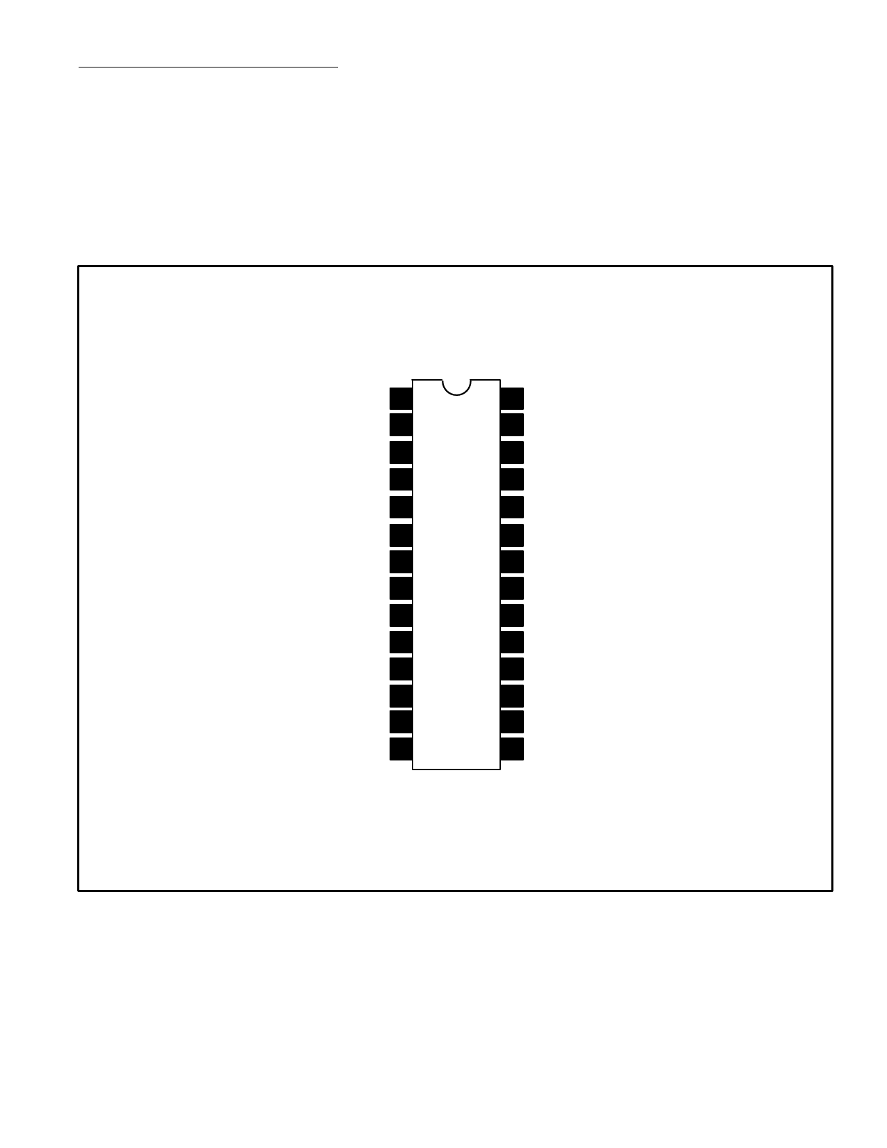
Pin Connection Diagram
AM & 10’s Hr ag & de 1
PM & 10’s Hr b 2
10’s Hr c & Hr c 3
Hr b & g 4
Hr c & d 5
Hr a & f 6
10’s Min a & f 7
10’s Min b & g 8
10’s Min c & d 9
10’s Min e & Min e 10
Min b & g 11
Min c & d 12
Min a & f 13
Colon Out 14
28 12/24 Hr Select
27 CR Input
26 50/60Hz Select
25 50/60Hz Input
24 Snooze Input
23 Sleep Input
22 Hour Set
21 Min Set
20 VDD
19 Alarm Disp
18 Alarm Off
17 Sleep Out
16 Alarm Out
15 VSS
Share Link: 