M74HC14YRM13TR View Datasheet(PDF) - STMicroelectronics
Part Name
Description
MFG CO.
M74HC14YRM13TR Datasheet PDF : 15 Pages
| |||
M74HC14
Electrical characteristics
Sym.
Parameter
Table 7. AC electrical characteristics
(CL = 50 pF, Input tr = tf = 6 ns)
Test
condition
Value
VCC
TA = 25 °C
-40 to 85 °C -55 to 125 °C Unit
(V)
Typ
Max
Max
Max
2.0
30
75
95
110
tTLH tTHL Output transition time
4.5
6.0
2.0
8
15
19
7
13
16
42
125
155
22
19
ns
190
tPLH tPHL Propagation delay time
4.5
14
25
31
38
6.0
12
21
16
32
Table 8. Capacitive characteristics
Test condition
Value
Sym
Parameter
VCC
(V)
TA = 25°C
Typ
Max
-40 to 85°C -55 to 125°C Unit
Max
Max
CIN Input capacitance
5
10
10
CPD
Power dissipation
capacitance(1)
5.0
fIN = 10 MHz 28
10
pF
1.
CcoPnDsuismdpetfiionnedwiathsotuhtelovaadlue(reoffetrhteo
IC’s
test
internal
circuit).
equivalent capacitance which is calculated
Average operating current can be obtained
from the operating current
by the following equation:
ICC(opr) = CPD x VCC x fIN + ICC/6(per gate).
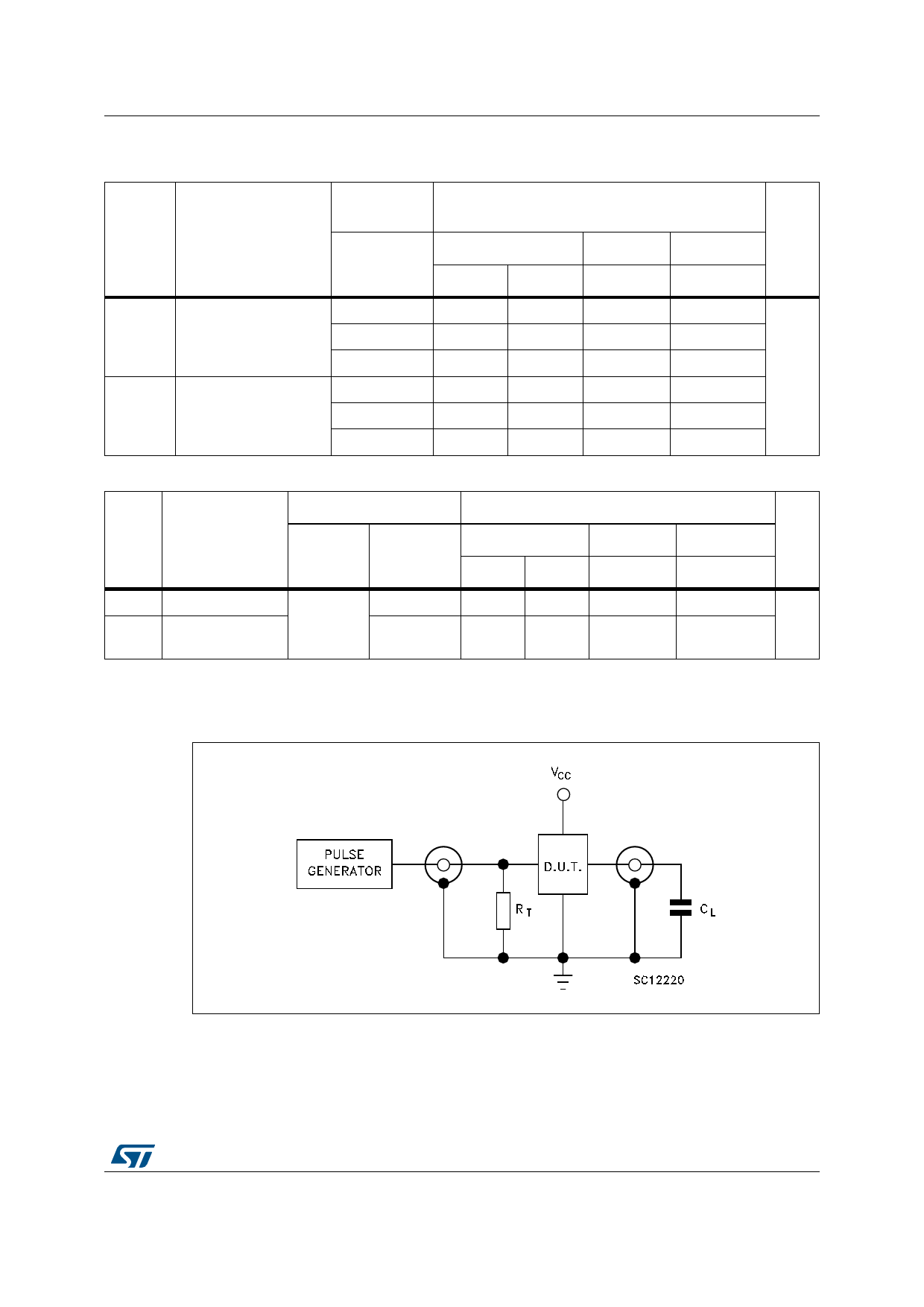
Figure 3. Test circuit
DocID1901 Rev 4
7/15
15
Share Link: 