74ACT125M(1997) View Datasheet(PDF) - STMicroelectronics
Part Name
Description
MFG CO.
74ACT125M Datasheet PDF : 8 Pages
| |||
74ACT125
AC ELECTRICAL CHARACTERISTICS (CL = 50 pF, RL = 500 Ω, Input tr = tf =3 ns)
Symbol
P ar ame te r
tPLH Propagation Delay Time
tPHL
tPZL Output Enable Time
tPZH
tPLZ Output Disable Time
tPHZ
(*) Voltage range is 5V ± 0.5V
Test Condition
V CC
(V)
5.0(*)
5.0(*)
5.0(*)
Value
TA = 25 oC
-40 to 85 oC
Min. Typ. Max. Min. Max.
1.0 6.5 9.0 1.0 10.0
Unit
ns
1.0 6.0 8.5 1.0 9.5 ns
1.0 7.0 9.5 1.0 10.5 ns
CAPACITIVE CHARACTERISTICS
Symbol
P ar ame te r
Test Conditions
V CC
(V)
Value
TA = 25 oC
-40 to 85 oC
Min. Typ. Max. Min. Max.
Unit
CIN Input Capacitance
5.0
4
pF
COUT Output Capacitance
5.0
8
pF
CPD Power Dissipation
5.0
Capacitance (note 1)
TBD
pF
1) CPD is defined as the value of the IC’s internal equivalent capacitance which is calculated from the operating current consumption without load. (Refer to
Test Circuit). Average operating current can be obtained by the following equation. ICC(opr) = CPD • VCC • fIN + ICC/n (per circuit)
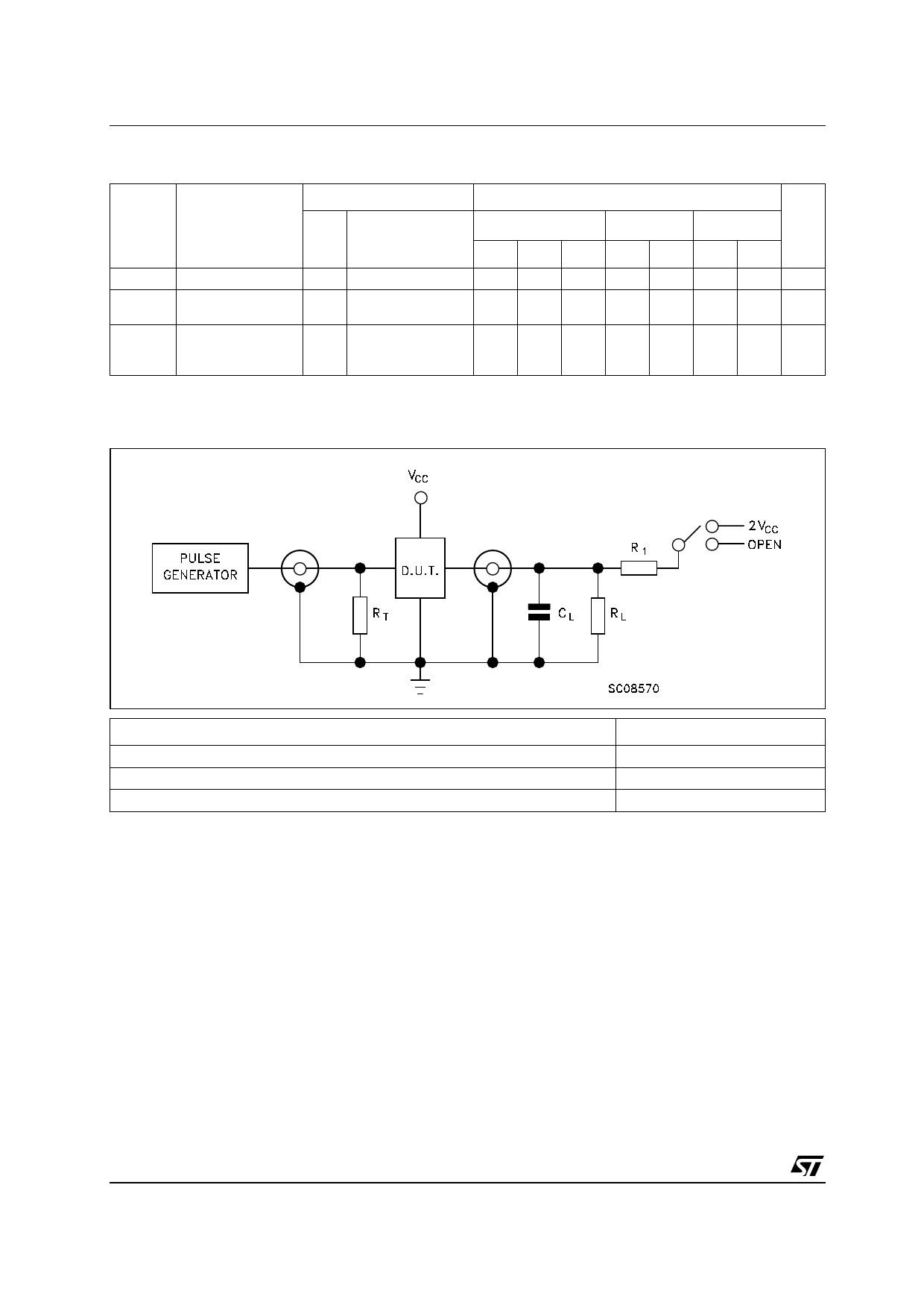
TEST CIRCUIT
T E ST
tPLH, tPHL
tPZL, tPLZ
tPZH, tPHZ
CL = 50 pF or equivalent (includes jig and probe capacitance)
RL = R1 = 500Ω or equivalent
RT = ZOUT of pulse generator (typically 50Ω)
4/8
SWITCH
Open
2VCC
Open
Share Link: 