SP4405EN View Datasheet(PDF) - Signal Processing Technologies
Part Name
Description
MFG CO.
SP4405EN
Signal Processing Technologies
SP4405EN Datasheet PDF : 20 Pages
| |||
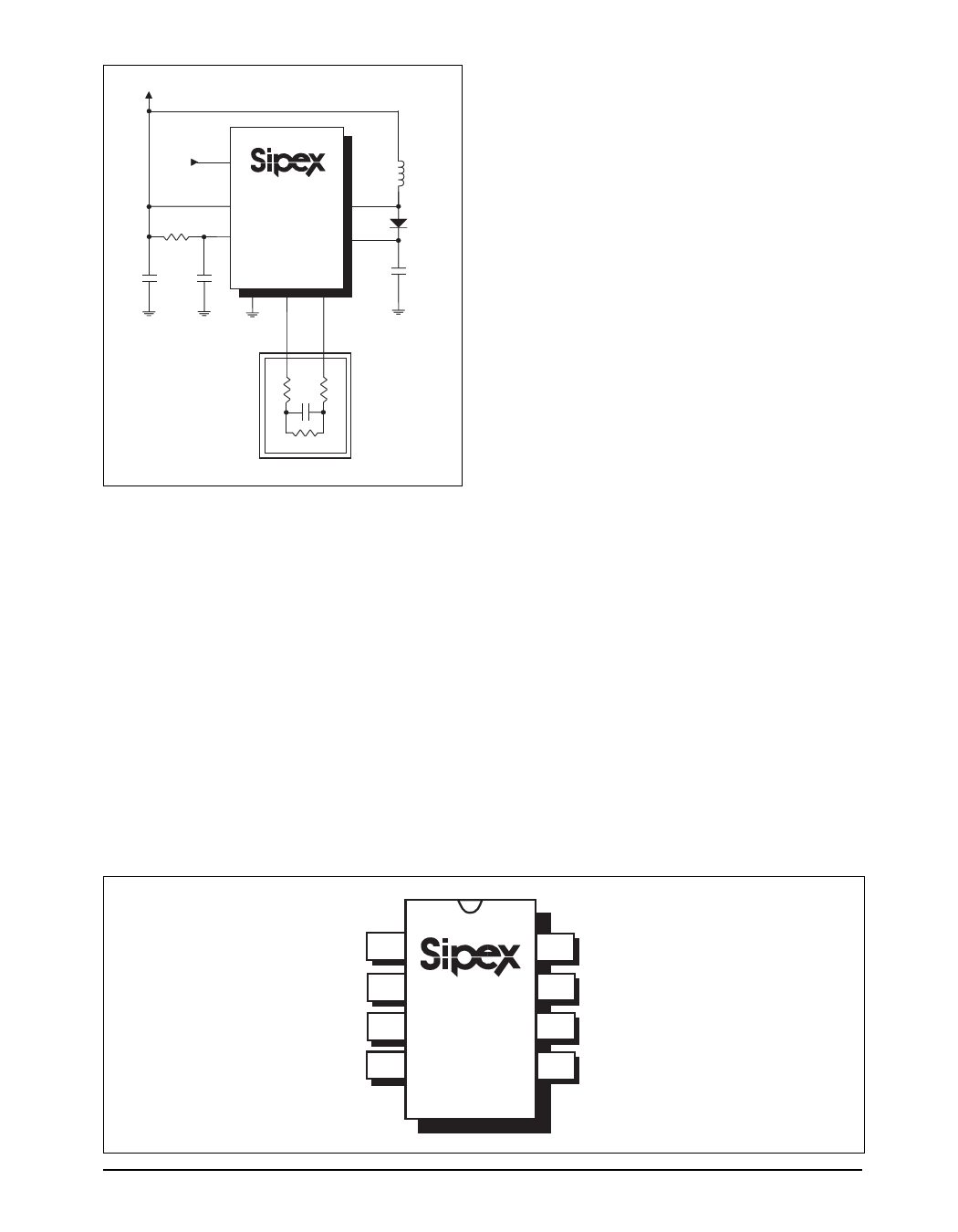
TEST CIRCUIT
VBATTERY
ELEN
1
ROSC
750kΩ
VDD 6
ROSC 8
SP4405
3
COIL
7
CINT
C1
C2
0.1µF
1nF
2
VSS
4
EL1
5
EL2
EL Lamp
L1
470µH
D1
1N4148
CINT
0.1µF
50Ω
50Ω
6.8nF
1MΩ
PIN ASSIGNMENTS
Pin 1 — ELEN — Eluminescent Lamp Enable.
When driven HIGH, this input pin enables
the EL driver output EL1 and EL2 (pins 4 and
5, respectively) to the EL lamp.
Pin 2 — VSS — Power Supply Common.
Connect to the lowest circuit potential,
typically ground.
Pin 3 — COIL — Coil. The inductor for the
EL lamp is connected from VBATTERY to this
input pin.
Pin 4 — EL1 — Eluminescent Lamp. This is
a lamp driver output pin to connect to the
EL lamp.
Pin 5 — EL2 — Eluminescent Lamp. This is
a lamp driver output pin to connect to the
EL lamp.
Pin 6 — VDD — Positive Battery Power Supply.
Connect such that +2.2V < V < +4.5V.
DD
Pin 7 — CINT — Integrating Capacitor.
Connecting a fast recovery diode from
COIL (pin 3) to this input pin increases
the light output of the EL lamp. An
integrating capacitor (0.1µF) connected
from this pin to ground filters out any coil
switching spikes or ripple present in the
output waveform to the EL lamp.
Pin 8 — ROSC — Oscillator Resistor. Connecting
a 450kΩ resistor to this input pin sets the
frequency of the internal clock.
PINOUT
ELEN 1
VSS 2
COIL 3
EL1 4
SP4405
8 ROSC
7 CINT
6 VDD
5 EL2
SP4405DS/18
SP4405 Low Voltage Electroluminescent Lamp Driver
3
© Copyright 2000 Sipex Corporation
Share Link: 