SL74HC4052 View Datasheet(PDF) - System Logic Semiconductor
Part Name
Description
MFG CO.
SL74HC4052
System Logic Semiconductor
SL74HC4052 Datasheet PDF : 9 Pages
| |||
SL74HC4052
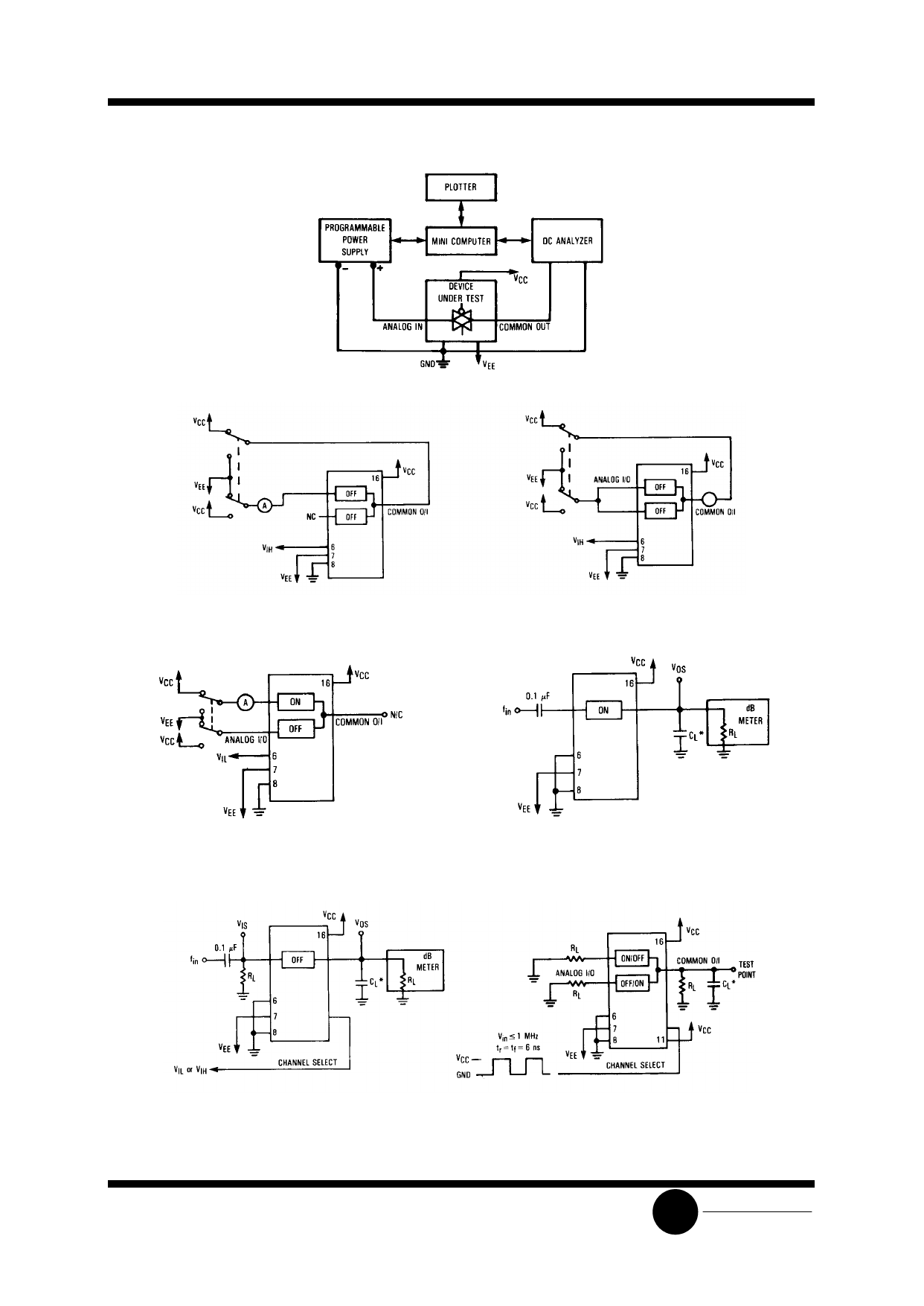
Figure 1. On Resistance Test Set-Up
Figure 2. Maximum Off Channel Leakage
Current, Any One Channel, Test Set-UP
Figure 3. Maximum Off Channel Leakage Current,
Common Channel, Test Set-UP
Figure 4. Maximum On Channel Leakage
Current, Channel to Channel, Test Set-UP
* Includes all probe and jig capacitance.
Figure 5. Maximum On Channel Bandwidth,
Test Set-UP
* Includes all probe and jig capacitance.
Figure 6. Off Channel Feedthrough Isolation,
Test Set-UP
* Includes all probe and jig capacitance.
Figure 7.Feedthrough Noise, Channel Select to Common
Out, Test Set-UP
SLS
System Logic
Semiconductor
Share Link: 