PNX3000HL View Datasheet(PDF) - Philips Electronics
Part Name
Description
MFG CO.
PNX3000HL Datasheet PDF : 51 Pages
| |||
Philips Semiconductors
Analog front end for digital video
processors
Preliminary specification
PNX3000
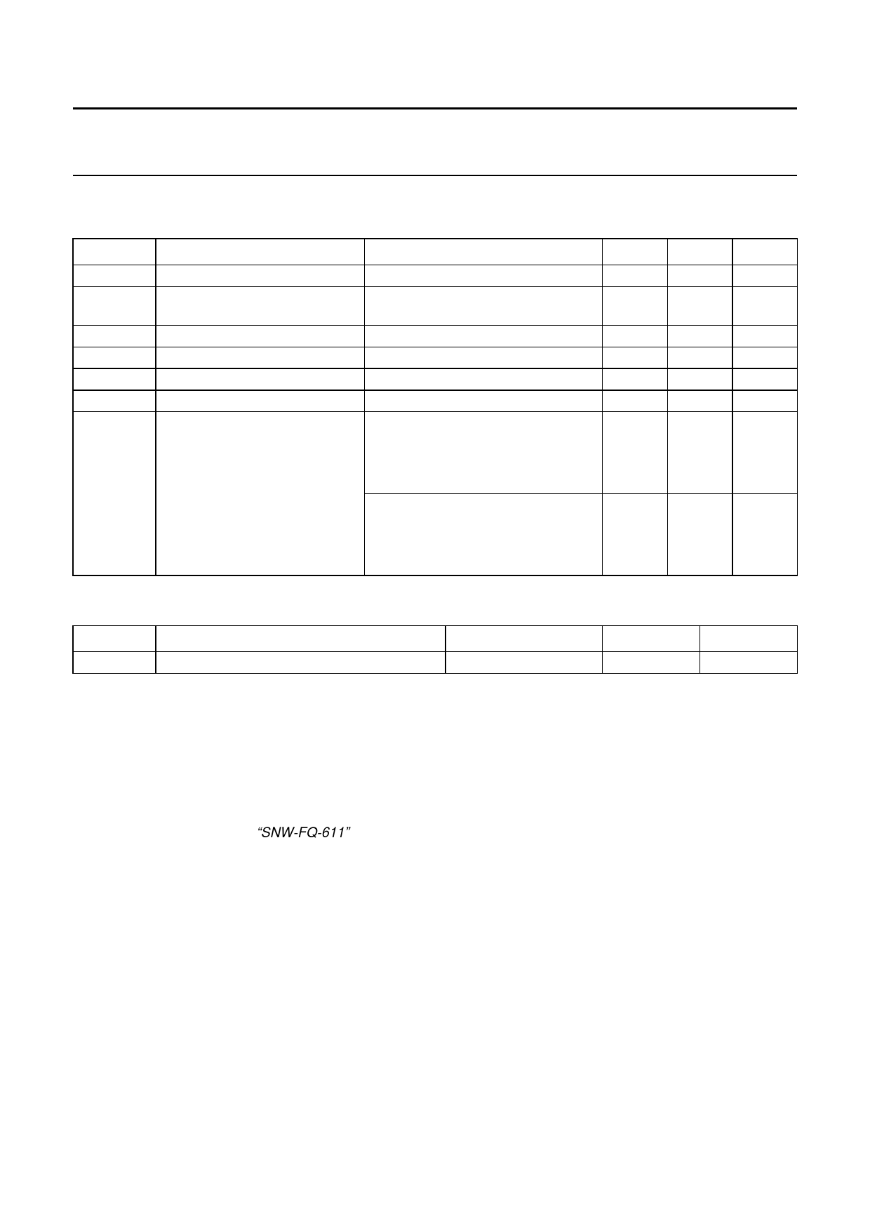
9 LIMITING VALUES
In accordance with the Absolute Maximum Rating System (IEC 60134).
SYMBOL
VP
VCC(1ASW),
VCC(2ASW)
Tstg
Tamb
Tsol
Tj
Vesd
PARAMETER
main supply voltage
audio supply voltage
storage temperature
ambient temperature
soldering temperature
operating junction temperature
electrostatic discharge voltage
CONDITIONS
for 5 s
Human Body Model; C = 100 pF;
R = 1.5 kΩ
pin SDA
all other pins
Machine Model; C = 200 pF;
R = 0 kΩ
pin SDA
all other pins
MIN.
−
−
MAX.
6.0
9.0
UNIT
V
V
−25
+150 °C
0
70
°C
−
260
°C
−
150
°C
−
±1500 V
−
±2000 V
−
−
±150 V
−
±200 V
10 THERMAL CHARACTERISTICS
SYMBOL
PARAMETER
CONDITIONS
VALUE
UNIT
Rth(j-a)
thermal resistance from junction to ambient in free air; note 1
30
K/W
Note
1. The value given for the thermal resistance from junction to ambient should only be considered as an indication. Most
of the dissipated heat is conveyed to the ambient air through the Printed-Circuit Board (PCB) on which the IC is
mounted. The actual value of the thermal resistance depends on the number of metal layers, size and layout of the
PCB, and also on the dissipation of other components on the PCB.
11 QUALITY SPECIFICATION
In accordance with document “SNW-FQ-611”.
11.1 Latch-up performance
At Tamb = 70 °C all pins meet the following specification:
• Positive stress test: Itrigger ≥ 100 mA or Vtrigger ≥ 1.5 VP(max)
• Negative stress test: Itrigger ≤ −100 mA or Vtrigger ≤ −0.5 VP(max).
2004 Oct 04
23
Share Link: 