M74HCT74B1R View Datasheet(PDF) - STMicroelectronics
Part Name
Description
MFG CO.
M74HCT74B1R Datasheet PDF : 10 Pages
| |||
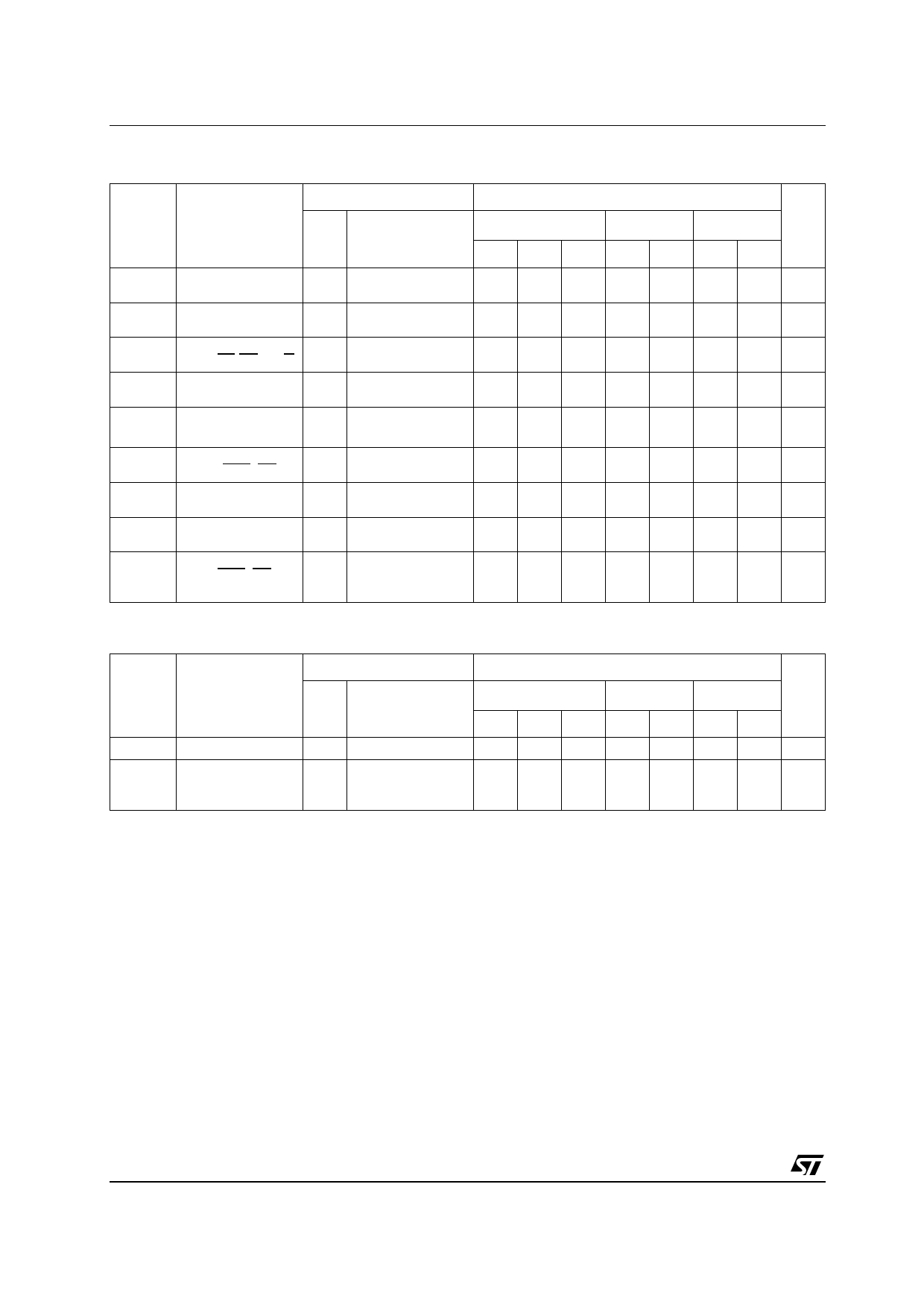
M74HCT74
AC ELECTRICAL CHARACTERISTICS (CL = 50 pF, Input tr = tf = 6ns)
Test Condition
Value
Symbol
Parameter
VCC
(V)
tTLH tTHL Output Transition
Time
4.5
tPLH tPHL Propagation Delay
Time (CLOCK-Q)
4.5
tPLH tPHL Propagation Delay
Time (CL,PR - Q,Q)
4.5
fMAX Maximum Clock
Frequency
4.5
tW(H)
tW(L)
Minimum Pulse
Width (CLOCK)
4.5
tW(L) Minimum Pulse
Width (CLR, PR)
4.5
ts
Minimum Set-Up
Time
4.5
th Minimum Hold
Time
4.5
tREM Minimum Removal
Time (CLR, PR to 4.5
CLOCK)
TA = 25°C
-40 to 85°C -55 to 125°C Unit
Min. Typ. Max. Min. Max. Min. Max.
8 15
19
22 ns
21 33
41
50 ns
18 30
38
45 ns
27 48
22
18
MHz
6 15
19
23 ns
8 15
19
23 ns
7 15
19
23 ns
0
0
0 ns
1
5
5
6
5
8 ns
CAPACITIVE CHARACTERISTICS
Test Condition
Value
Symbol
Parameter
VCC
(V)
TA = 25°C
-40 to 85°C -55 to 125°C Unit
Min. Typ. Max. Min. Max. Min. Max.
CIN Input Capacitance
CPD Power Dissipation
Capacitance (note
1)
5 10
10
10 pF
32
pF
1) CPD is defined as the value of the IC’s internal equivalent capacitance which is calculated from the operating current consumption without
load. (Refer to Test Circuit). Average operating current can be obtained by the following equation. ICC(opr) = CPD x VCC x fIN + ICC/2 (per FLIP/
FLOP)
4/10
Share Link: 