LTC2240CUP-10PBF View Datasheet(PDF) - Linear Technology
Part Name
Description
MFG CO.
LTC2240CUP-10PBF Datasheet PDF : 28 Pages
| |||
LTC2240-10
APPLICATIONS INFORMATION
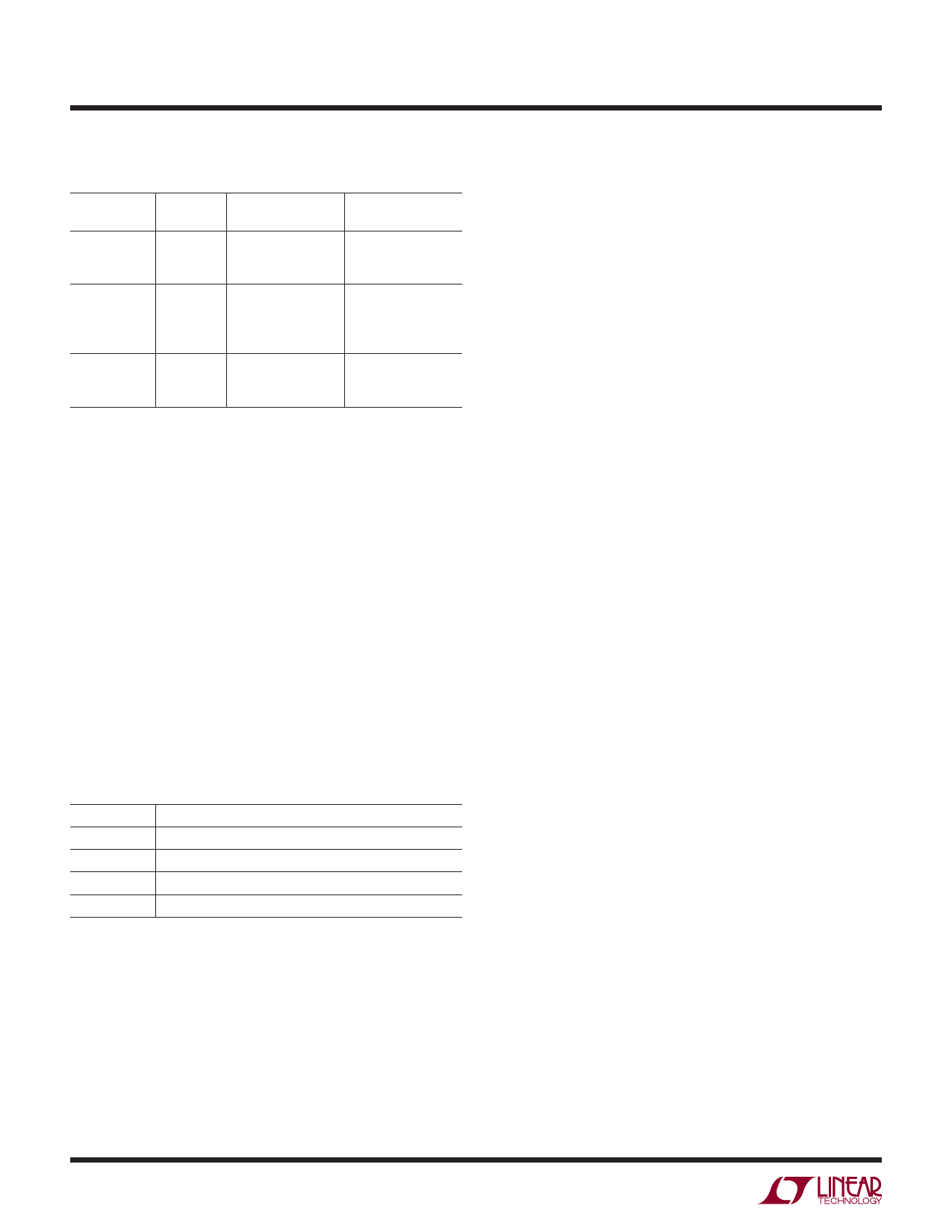
Table 1. Output Codes vs Input Voltage
AIN+ – AIN–
(2V Range)
OF
D9 – D0
(Offset Binary)
>+1.000000V
1
+0.998047V
0
+0.996094V
0
11 1111 1111
11 1111 1111
11 1111 1110
+0.001953V
0
0.000000V
0
–0.001953V
0
–0.003906V
0
10 0000 0001
10 0000 0000
01 1111 1111
01 1111 1110
–0.998047V
0
–1.000000V
0
<–1.000000V
1
00 0000 0001
00 0000 0000
00 0000 0000
D9 – D0
(2’s Complement)
01 1111 1111
01 1111 1111
01 1111 1110
00 0000 0001
00 0000 0000
11 1111 1111
11 1111 1110
10 0000 0001
10 0000 0000
10 0000 0000
Digital Output Modes
The LTC2240-10 can operate in several digital output
modes: LVDS, CMOS running at full speed, and CMOS
demultiplexed onto two buses, each of which runs at half
speed. In the demultiplexed CMOS modes the two buses
(referred to as bus A and bus B) can either be updated on
alternate clock cycles (interleaved mode) or simultaneously
(simultaneous mode). For details on the clock timing, refer
to the timing diagrams.
The LVDS pin selects which digital output mode the part
uses. This pin has a four-level logic input which should
be connected to GND, 1/3VDD, 2/3VDD or VDD. An external
resistor divider can be used to set the 1/3VDD or 2/3VDD
logic values. Table 2 shows the logic states for the LVDS
pin.
Table 2. LVDS Pin Function
LVDS
DIGITAL OUTPUT MODE
GND
Full-Rate CMOS
1/3VDD
2/3VDD
VDD
Demultiplexed CMOS, Simultaneous Update
Demultiplexed CMOS, Interleaved Update
LVDS
Digital Output Buffers (CMOS Modes)
Figure 13a shows an equivalent circuit for a single
output buffer in the CMOS output mode. Each buffer is
powered by OVDD and OGND, which are isolated from the
ADC power and ground. The additional N-channel transistor
in the output driver allows operation down to voltages as
low as 0.5V. The internal resistor in series with the output
makes the output appear as 50Ω to external circuitry and
may eliminate the need for external damping resistors.
As with all high speed/high resolution converters, the
digital output loading can affect the performance. The
digital outputs of the LTC2240-10 should drive a minimal
capacitive load to avoid possible interaction between the
digital outputs and sensitive input circuitry. The output
should be buffered with a device such as an 74VCX245
CMOS latch. For full speed operation the capacitive load
should be kept under 10pF.
Lower OVDD voltages will also help reduce interference
from the digital outputs.
Digital Output Buffers (LVDS Mode)
Figure 13b shows an equivalent circuit for a differential
output pair in the LVDS output mode. A 3.5mA current is
steered from OUT+ to OUT– or vice versa which creates a
±350mV differential voltage across the 100Ω termination
resistor at the LVDS receiver. A feedback loop regulates
the common mode output voltage to 1.25V. For proper
operation each LVDS output pair needs an external 100Ω
termination resistor, even if the signal is not used (such
as OF+/OF– or CLKOUT+/CLKOUT–). To minimize noise
the PC board traces for each LVDS output pair should be
routed close together. To minimize clock skew all LVDS PC
board traces should have about the same length.
20
224010fb
Share Link: 