SY100E154 View Datasheet(PDF) - Micrel
Part Name
Description
MFG CO.
SY100E154 Datasheet PDF : 4 Pages
| |||
Micrel, Inc.
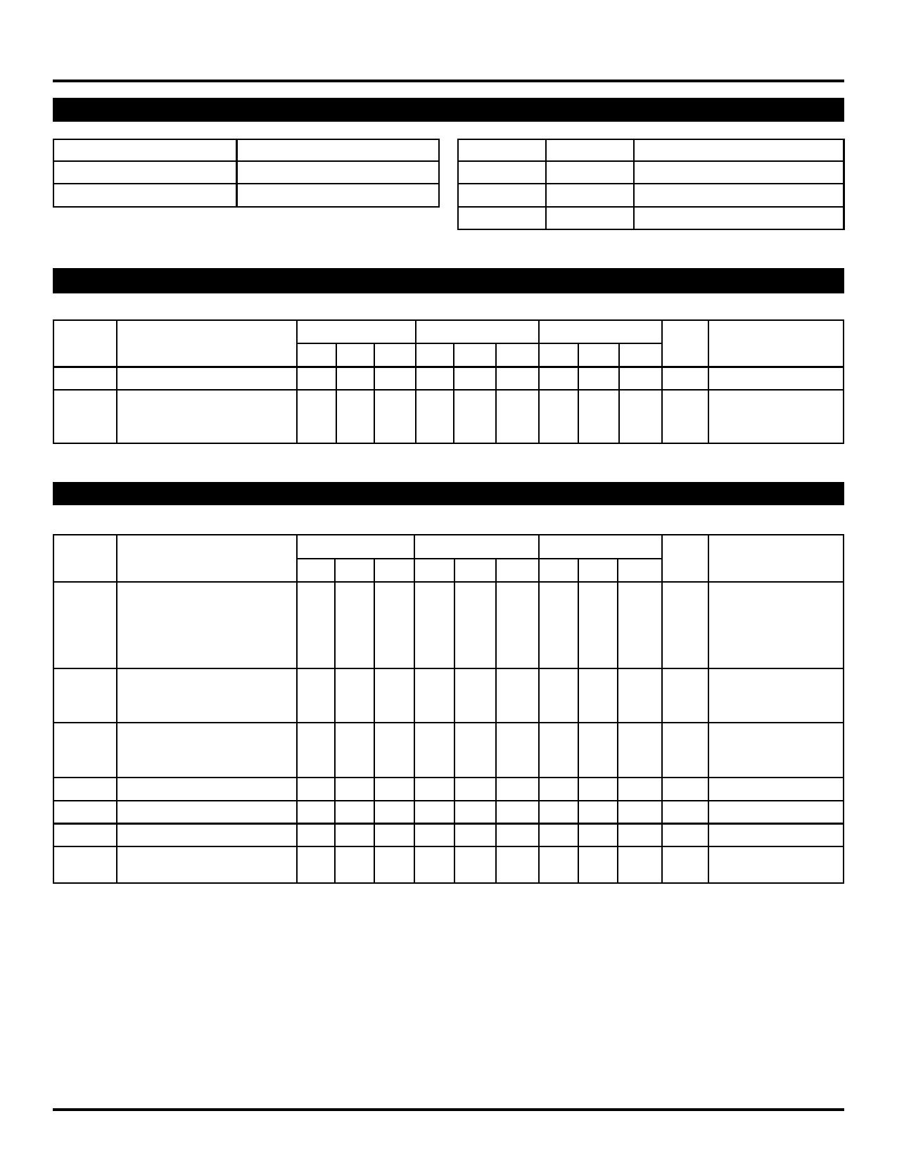
TRUTH TABLES
SEL
Data
H
a
L
b
LEN1
L
H
X
LEN2
L
X
H
SY10E154
SY100E154
Latch
Transparent
Latched
Latched
DC ELECTRICAL CHARACTERISTICS
VEE = VEE (Min.) to VEE (Max.); VCC = VCCO = GND
TA = 0°C
TA = +25°C
TA = +85°C
Symbol
Parameter
Min. Typ. Max. Min. Typ. Max. Min. Typ. Max. Unit
IIH
Input HIGH Current
— — 150 — — 150 — — 150 µA
IEE
Power Supply Current
mA
10E — 76 91 — 76 91 — 76 91
100E — 76 91 — 76 91 — 87 105
Condition
—
—
AC ELECTRICAL CHARACTERISTICS
VEE = VEE (Min.) to VEE (Max.); VCC = VCCO = GND
TA = 0°C
TA = +25°C
TA = +85°C
Symbol
Parameter
Min. Typ. Max. Min. Typ. Max. Min. Typ. Max. Unit
tPD
Propagation Delay to Output
ps
D
325 500 700 325 500 700 325 500 700
SEL
475 650 925 475 650 925 475 650 925
LEN
350 500 750 350 500 750 350 500 750
MR
450 600 800 450 600 800 450 600 800
tS
Set-up Time
D
SEL
ps
300 100 — 300 100 — 300 100 —
500 250 — 500 250 — 500 250 —
tH
Hold Time
D
SEL
ps
300 –100 — 300 –100 — 300 –100 —
200 –250 — 200 –250 — 200 –250 —
tRR
Reset Recovery Time
800 600 — 800 600 — 800 600 — ps
tPW
Minimum Pulse Width, MR 400 — — 400 — — 400 — — ps
tskew
Within-Device Skew
— 50 — — 50 — — 50 — ps
tr
Rise/Fall Time
tf
20% to 80%
300 475 800 300 475 800 300 475 800 ps
Note:
1. Within-device skew is defined as identical transitions on similar paths through a device.
Condition
—
—
—
—
—
1
—
M9999-032006
hbwhelp@micrel.com or (408) 955-1690
3
Share Link: 