2N5786 View Datasheet(PDF) - Semelab - > TT Electronics plc
Part Name
Description
MFG CO.
2N5786 Datasheet PDF : 2 Pages
| |||
2N5786
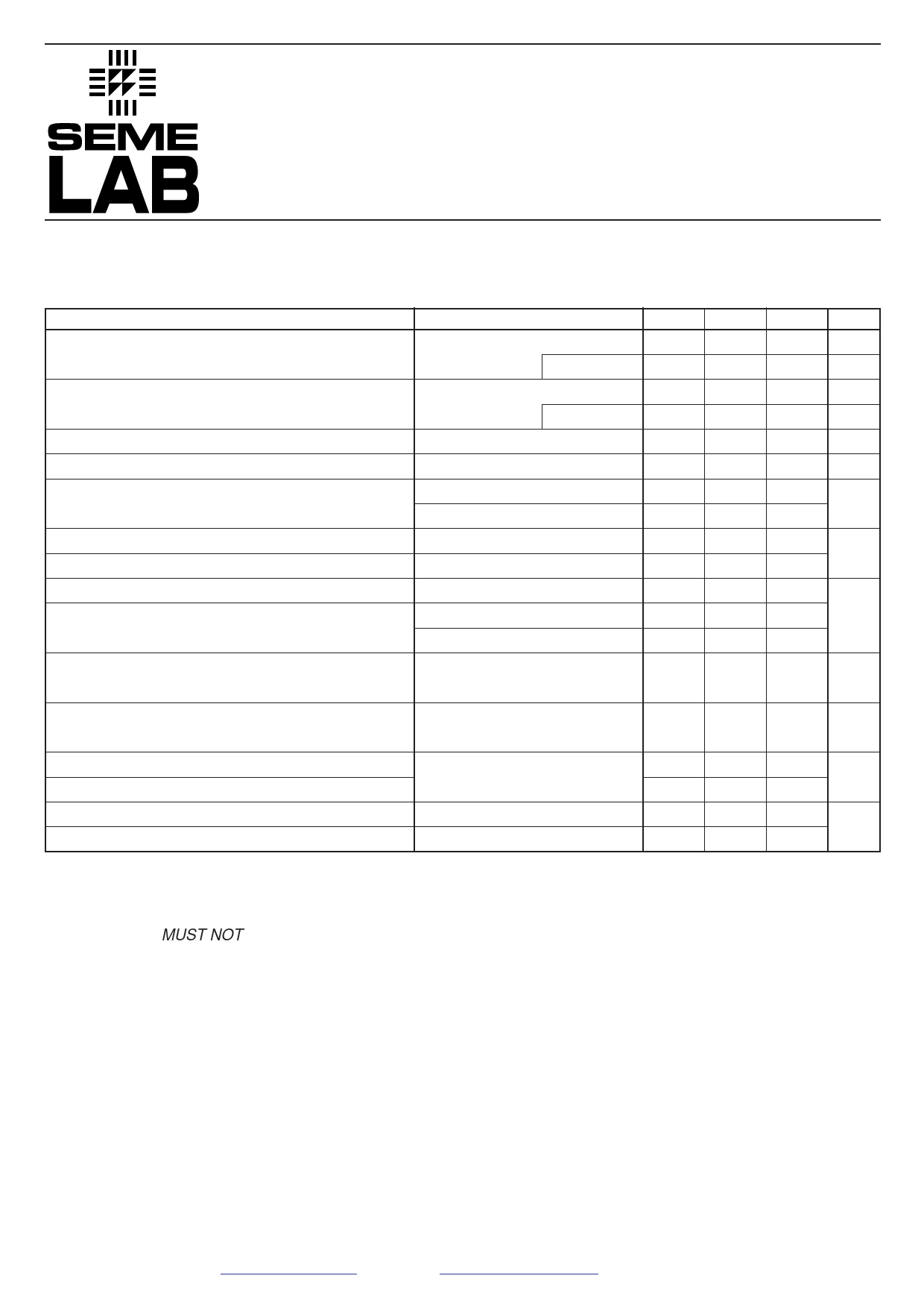
ELECTRICAL CHARACTERISTICS (TC = 25°C unless otherwise stated)
Parameter
Test Conditions
Min.
ICER
Collector Cut-off Current
VCE = 40V
RBE = 100Ω
TC = 150°C
ICEX
Collector Cut-off Current
VCE = 45V
RBE = 100Ω
VBE = -1.5V
TC = 150°C
ICEO
Collector Cut-off Current
VCE = 25V
IB = 0
IEBO
Emitter Cut-off Current
VBE = -3.5V
IC = 0
hFE*
DC Current Gain
VCE = 2V
VCE = 2V
IC = 1.6A
20
IC = 3.2A
4
VCEO(sus)* Collector – Emitter Sustaining Voltage 1 IC = 0.1A
IB = 0
40
VCER(sus)* Collector – Emitter Sustaining Voltage 1 IC = 0.1A
RBE = 100Ω 45
VBE
Base – Emitter Voltage
VCE = 2V
IC = 1.6A
VCE(sat) Collector – Emitter Saturation Voltage 2 IC = 1.6A
IB = 0.16mA
IC = 3.2A
IB = 0.8mA
hfe
Small Signal Common – Emitter
Current Gain
VCE = -2V
f = 200kHz
IC = 100mA
5
hfe
Small Signal Common – Emitter
VCE = 2V
IC = 100mA
25
Current Gain
f = 1kHz
tON
tOFF
RθJC
RθJA
Turn-on Time
Turn-off Time
Thermal Resistance Junction – Case
VCC = 30V
IB1 = IB2
Thermal Resistance Junction – Ambient
IC = 1A
NOTES
* Pulse Test: tp = 300µs, δ = 1.8%.
1) These tests MUST NOT be measured on a curve tracer.
2) Measured 1/4” (6.35 mm) from case. Lead resistance is critical in this test.
3) Measured at a frequency where hfe is decreasing at approximately 6dB per octave.
Typ.
Max. Unit
10
µA
1 mA
10 µA
1 mA
100 µA
10 µA
100
—
V
1.5
1
V
2
20 —
—
5
µs
15
17.5
°C/W
175
Semelab Plc reserves the right to change test conditions, parameter limits and package dimensions without notice. Information furnished by Semelab is believed
to be both accurate and reliable at the time of going to press. However Semelab assumes no responsibility for any errors or omissions discovered in its use.
Semelab encourages customers to verify that datasheets are current before placing orders.
Semelab plc. Telephone +44(0)1455) 556565. Fax +44(0)1455) 552612.
E-mail: sales@semelab.co.uk Website: http://www.semelab.co.uk
Document Number 3079
Issue: 1
Share Link: 