ICS85214AG View Datasheet(PDF) - Integrated Circuit Systems
Part Name
Description
MFG CO.
ICS85214AG Datasheet PDF : 16 Pages
| |||
Integrated
Circuit
Systems, Inc.
ICS85214
LOW SKEW, 1-TO-5
DIFFERENTIAL-TO-HSTL FANOUT BUFFER
TABLE 3A. CONTROL INPUT FUNCTION TABLE
Inputs
Outputs
nCLK_EN
Q0:Q4
nQ0:nQ4
0
Enabled
Enabled
1
Disabled; LOW
Disabled; HIGH
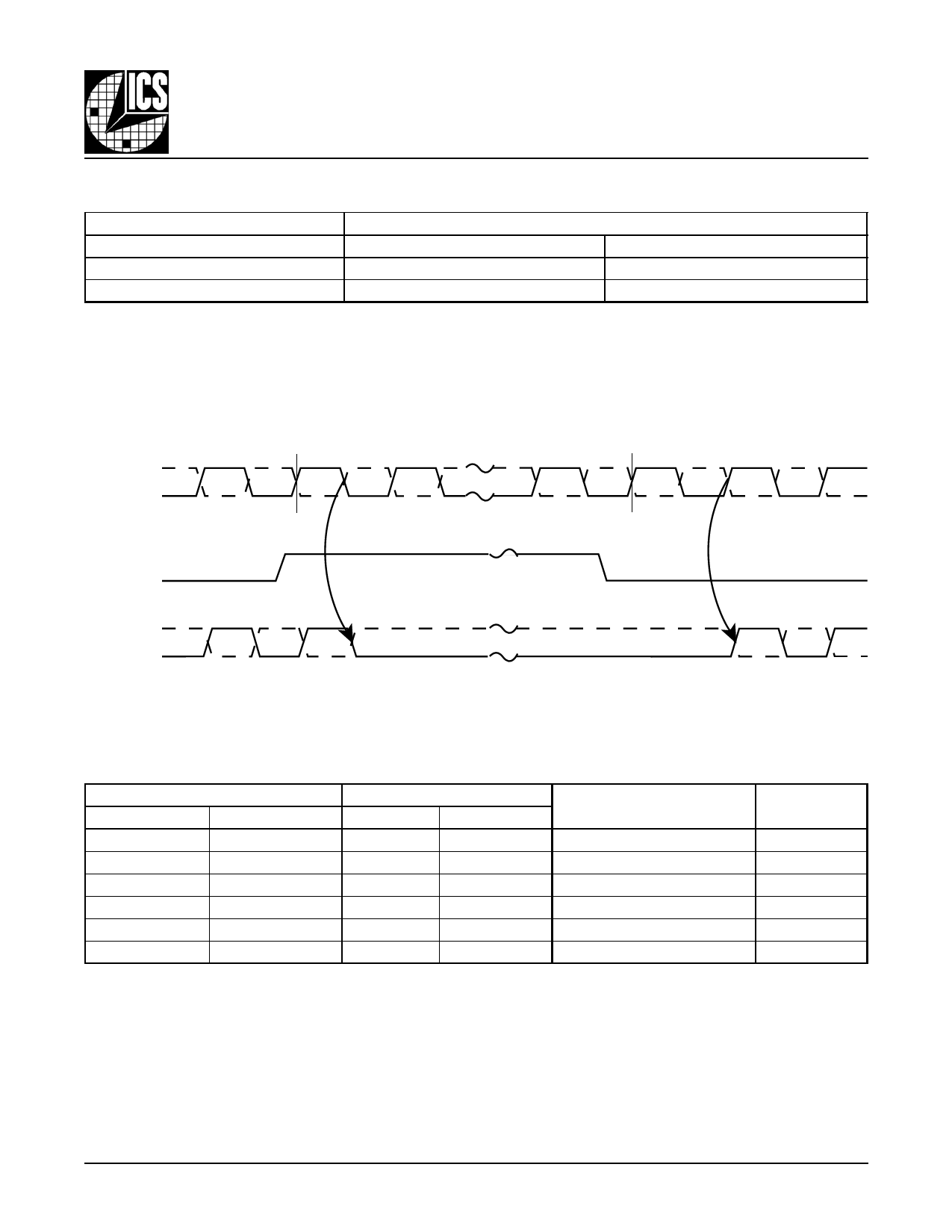
After nCLK_EN switches, the clock outputs are disabled or enabled following a rising and falling input clock edge
as shown in Figure 1.
In the active mode, the state of the outputs are a function of the CLK0, nCLK0 inputs as described in Table 3B.
nCLK0
CLK0
Disabled
Enabled
nCLK_EN
nQ0:nQ4
Q0:Q4
FIGURE 1. nCLK_EN TIMING DIAGRAM
TABLE 3B. CLOCK INPUT FUNCTION TABLE
Inputs
CLK0, CLK1
nCLK0
Outputs
Q0:Q4
nQ0:nQ4
Input to Output Mode
Polarity
0
1
LOW
HIGH
Differential to Differential
Non Inverting
1
0
HIGH
LOW
Differential to Differential
Non Inverting
0
Biased; NOTE 1
LOW
HIGH
Single Ended to Differential Non Inverting
1
Biased; NOTE 1
HIGH
LOW
Single Ended to Differential Non Inverting
Biased; NOTE 1
0
HIGH
LOW
Single Ended to Differential
Inverting
Biased; NOTE 1
1
LOW
HIGH
Single Ended to Differential
Inverting
NOTE 1: Please refer to the Application Information section, "Wiring the Differential Input to Accept Single Ended Levels".
85214AG
www.icst.com/products/hiperclocks.html
3
REV. A JULY 17, 2003
Share Link: 