DS1372 View Datasheet(PDF) - Maxim Integrated
Part Name
Description
MFG CO.
DS1372 Datasheet PDF : 12 Pages
| |||
I2C, 32-Bit, Binary Counter Clock with 64-Bit ID
Detailed Description
The DS1372 is a 32-bit binary counter designed to con-
tinuously count time in seconds. An additional counter
is provided that can generate a periodic alarm. An
interrupt output can be driven when the alarm condition
is met. The device includes a unique, factory-lasered
64-bit ROM ID. The device is programmed serially by
an I2C bidirectional bus.
Oscillator Circuit
The DS1372 is designed to operate with a standard
32.768kHz quartz crystal having a 12.5pF specified
load capacitance (CL). For more information on crystal
selection and crystal layout considerations, refer to
Application Note 58: Crystal Considerations with Dallas
Real-Time Clocks (RTCs). An external 32.768kHz oscil-
lator can be used as the DS1372’s time base. In this
configuration, the X1 pin is connected to the external
oscillator signal and the X2 is floated. The EOSC bit in
the Control Register controls oscillator operation.
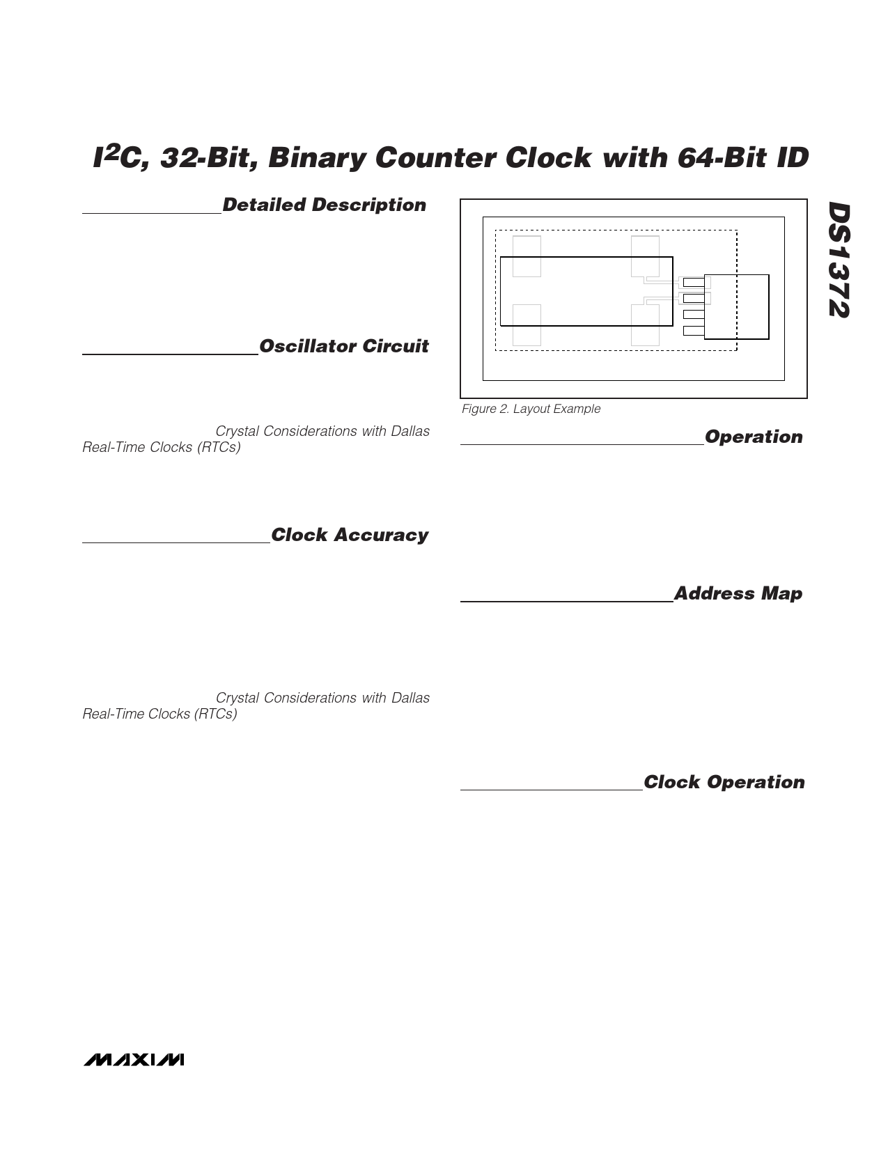
Clock Accuracy
The initial clock accuracy is dependent upon the accu-
racy of the crystal and the accuracy of the match
between the capacitive load of the oscillator circuit and
the capacitive load for which the crystal was trimmed.
Additional error is added by crystal frequency drift
caused by temperature shifts. External circuit noise cou-
pled into the oscillator circuit can result in the clock run-
ning fast. Figure 2 shows a typical PCB layout for
isolation of the crystal and oscillator from noise. Refer to
Application Note 58: Crystal Considerations with Dallas
Real-Time Clocks (RTCs) for detailed information.
X1
CRYSTAL
X2
LOCAL GROUND PLANE (LAYER 2)
Figure 2. Layout Example
Operation
The block diagram in Figure 1 shows the DS1372’s main
elements. As shown, communications to and from the
DS1372 occur serially over an I2C bidirectional bus. The
DS1372 operates as a slave device on the serial bus.
Access is obtained by implementing a START condition
and providing a device identification code followed by a
register address. Subsequent registers can be accessed
sequentially until a STOP condition is executed.
Address Map
Table 1 shows the address map for the DS1372 regis-
ters. During a multibyte access, when the address
pointer reaches the end of the register space (10h) it
wraps around to location 00h. On an I2C START or
address pointer incrementing to location 00h, the cur-
rent time is transferred to a second set of registers. The
time information is read from these secondary registers,
while the clock may continue to run. This eliminates the
need to reread the registers in case the main registers
update during a read.
Clock Operation
The clock counter is a 32-bit up counter. The counter
counts up once per second. The contents can be read
or written by accessing the address range 00h–03h. On
an I2C START, or when the address pointer rolls over to
00h, the current value is latched into a register, which is
output on the serial data line while the counter contin-
ues to increment. When writing to the registers, the
divider chain is reset when register 00h is written. Once
the divider chain is reset, the remaining clock registers
should be written within one second to avoid rollover
issues. Additionally, to avoid rollover issues the clock
registers must also be written from LSB to MSB, and all
four bytes should always be written.
_______________________________________________________________________________________ 5
Share Link: 