74LVC1G58GV View Datasheet(PDF) - Philips Electronics
Part Name
Description
MFG CO.
74LVC1G58GV Datasheet PDF : 18 Pages
| |||
Philips Semiconductors
74LVC1G58
Low-power configurable multiple function gate
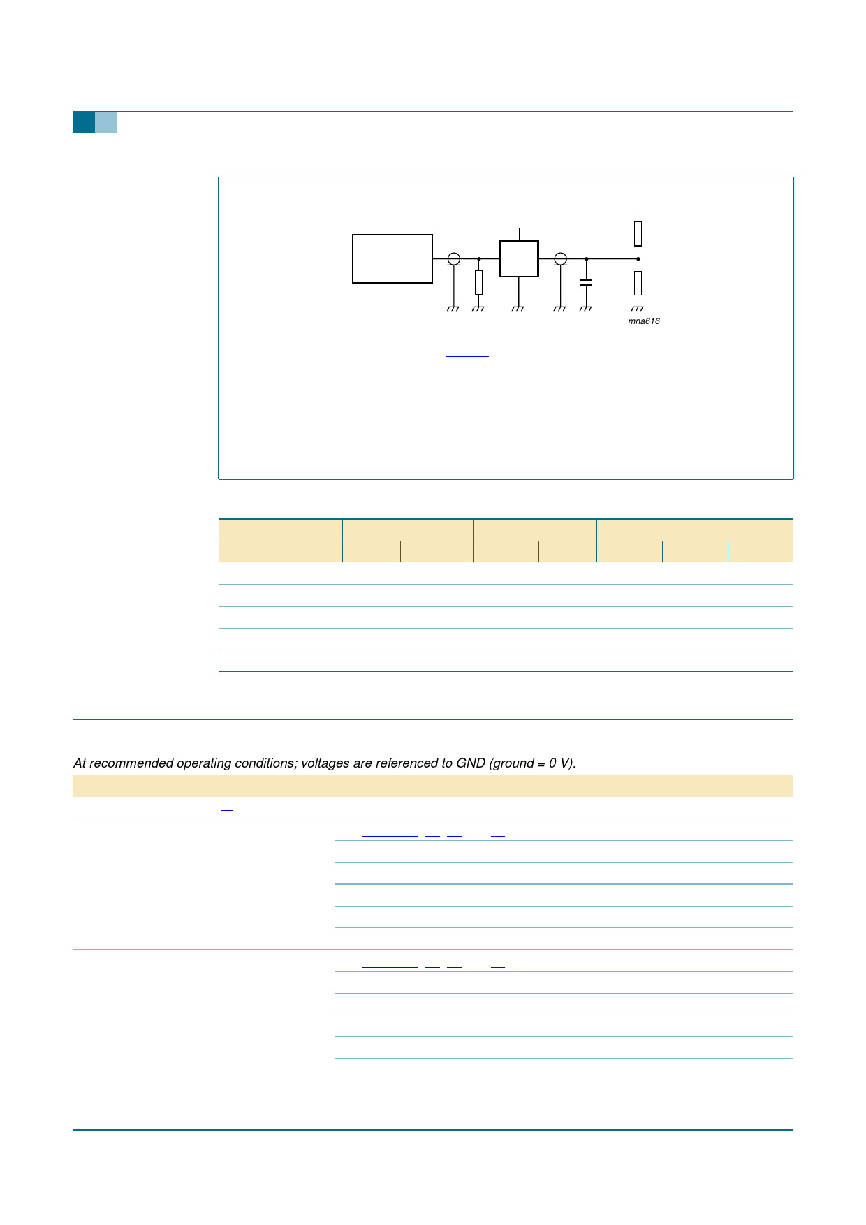
VCC
VI
PULSE
GENERATOR
VO
D.U.T.
RT
VEXT
RL
CL
RL
mna616
Measurement points are given in Table 12.
Definitions for test circuit:
RT = Termination resistance should be equal to output impedance Zo of the pulse generator.
CL = Load capacitance including jig and probe capacitance.
RL = Load resistor.
VEXT = Test voltage for switching times.
Fig 12. Load circuitry for switching times.
Table 12: Measurement points
Supply voltage Input
VCC
1.65 V to 1.95 V
2.3 to 2.7 V
2.7 V
VI
VCC
VCC
2.7 V
tr = tf
≤ 2.0 ns
≤ 2.0 ns
≤ 2.5 ns
3.0 V to 3.6 V
2.7 V ≤ 2.5 ns
4.5 V to 5.5 V
VCC
≤ 2.5 ns
Load
CL
30 pF
30 pF
50 pF
50 pF
50 pF
RL
1 kΩ
500 Ω
500 Ω
500 Ω
500 Ω
VEXT
tPLH, tPHL tPZH, tPHZ tPZL, tPLZ
open
GND
2 × VCC
open
GND
2 × VCC
open
GND
6V
open
GND
6V
open
GND
2 × VCC
14. Transfer characteristics
Table 13: Transfer characteristics
At recommended operating conditions; voltages are referenced to GND (ground = 0 V).
Symbol Parameter
Conditions
Min Typ Max Unit
Tamb = −40 °C to +85 °C [1]
VT+
positive-going threshold
voltage
VT−
negative-going threshold
voltage
see Figure 13, 14, 15 and 16
VCC = 1.8 V
VCC = 2.3 V
VCC = 3.0 V
VCC = 4.5 V
VCC = 5.5 V
see Figure 13, 14, 15 and 16
VCC = 1.8 V
VCC = 2.3 V
VCC = 3.0 V
VCC = 4.5 V
VCC = 5.5 V
0.70 1.02 1.20 V
1.11 1.42 1.60 V
1.50 1.79 2.00 V
2.16 2.52 2.74 V
2.61 2.99 3.33 V
0.30 0.53 0.72 V
0.58 0.77 1.00 V
0.80 1.04 1.30 V
1.21 1.55 1.90 V
1.45 1.86 2.29 V
9397 750 13852
Product data sheet
Rev. 01 — 15 September 2004
© Koninklijke Philips Electronics N.V. 2004. All rights reserved.
10 of 18
Share Link: 