SC2446EVB View Datasheet(PDF) - Semtech Corporation
Part Name
Description
MFG CO.
SC2446EVB Datasheet PDF : 38 Pages
| |||
SC2446
POWER MANAGEMENT
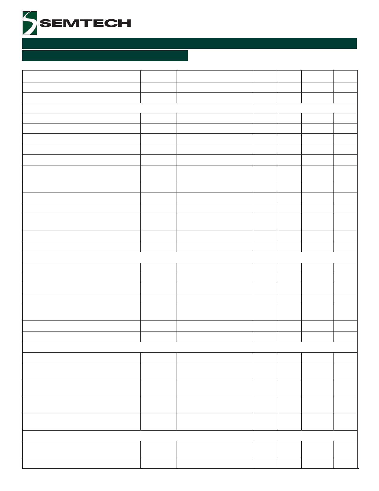
Electrical Characteristics (Cont.)
Unless specified: AVCC = PVCC = VIN2 =12V, VBST1 = VBST2 = 12V, SYNC= 0, ROSC = 51.1kΩ, -40°C < TA = TJ < 85°C
Parameter
Symbol
Conditions
Min
Amplifier Output Sink Current
Amplifier Output Source Current
Channel 2 Error Amplifier
VIN1- = 1V, VCOMP1 = 2.5V
VIN1- = 0, VCOMP1 = 2.5V
Input Common-mode Voltage Range
(Note 1)
0
Inverting Input Voltage Range
(Note 1)
0
Input Offset Voltage
Non-inverting Input Bias Current
IIN2+
Inverting Input Bias Current
IIN2-
Inverting Input Voltage for 2-Phase Single
Output Operation
2.5
Amplifier Transconductance
GM2
Amplifier Open-Loop Gain
aOL2
Amplifier Unity Gain Bandwidth
Minimum COMP2 Switching Threshold
Amplifier Output Sink Current
Amplifier Output Source Current
Oscillator
VVSCSS22+In=cVreCaS2s-in=g0
VCOMP2 = 2.5V
VCOMP2 = 2.5V
Channel Frequency
Synchronizing Frequency
fCH1, fCH2
(Note 1)
SYNC Input High Voltage
SYNC Input Low Voltage
SYNC Input Current
Channel Maximum Duty Cycle
Channel Minimum Duty Cycle
Current-limit Comparators
ISYNC
D D MAX1, MAX2
D D MIN1, MIN2
VSYNC
VSYNC
=
=
0.2V
2V
Input Common-Mode Range
Cycle-by-cycle Peak Current Limit
Valley Current Overload Shutdown
Threshold
VILIM1+,
VILIM2+
V V ILIM1-, ILIM2-
SVoCuS1r-c=ingVCMS2o- =de0.5V,
SVinCkS1in- =g MVCoSd2-e= 0.5V,
Positive Current-Sense Input Bias Current
Negative Current-Sense Input Bias
Current
Gate Drivers
I I CS1+, CS2+
I I CS1-, CS2-
VCS1+
VCS2-
==VVCCSS21--
=
=
0
0
VCS1+
VCS2+
=
=
VCS1-
VCS2-
=
=
0
0
450
2.1fCH
1.5
0
60
-85
High-side Gate Drive Peak Source
Current
High-side Gate Drive Peak Sink Current
2004 Semtech Corp.
VBST1 ,VBST2 = 12V
VBST1 ,VBST2 = 12V
3
Typ
16
12
1.5
-150
-100
260
65
5
2.2
16
12
500
88
75
-110
-0.7
-0.7
1.5
1
Max Units
µA
µA
3
AVCC
±3
-380
-250
V
V
mV
nA
nA
V
µΩ−1
dΒ
MHz
V
µA
µA
550
KHz
KHz
V
0.5
V
1
100
µA
%
0
%
AVCC - 1 V
90
mV
-130
mV
-2
µA
-2
µA
A
A
www.semtech.com
Share Link: 