1N5908RL View Datasheet(PDF) - STMicroelectronics
Part Name
Description
MFG CO.
1N5908RL Datasheet PDF : 6 Pages
| |||
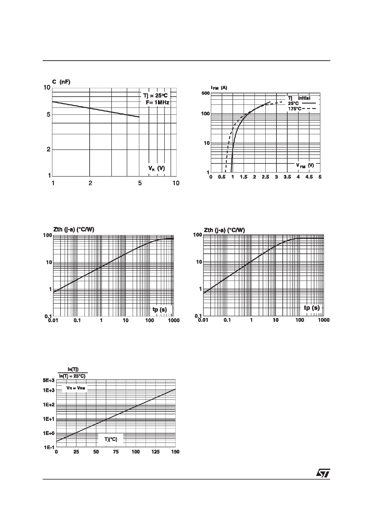
1N5908/SM5908
Fig. 4 : Capacitance versus reverse applied
voltage (typical values).
Fig. 5 : Peak forward voltage drop versus peak
forward current.
Fig. 6a/6b : Transient thermal impedance junction-ambientversus pulse duration.
Fig. 6a : CB429 Package.
(For FR4 PC Board with L lead = 10 mm)
Fig. 6b : SMC Package.
Mounting on FR4 PC Board with recommended
pad layout.
Fig. 7 : Relative variation of leakage current
versus junction temperature.
4/6
Share Link: 