VP453 View Datasheet(PDF) - SANYO -> Panasonic
Part Name
Description
View to exact match
VP453 Datasheet PDF : 5 Pages
| |||
VP453
Sample Thermal Design for the VP453
Conditions: For an fH = 95 kHz class monitor, fV = 120 MHz (clock).
VCC = 80 V, VOUT = 40 Vp-p (CL = 10 pF)
Here we consider the case where such a monitor is to be operated at ambient temperatures up to Ta = 60°C and at a
maximum frequency of f = 100 MHz (clock).
As mentioned previously, the chips with the maximum loss will be transistors 3 and 4 in the emitter-follower stage.
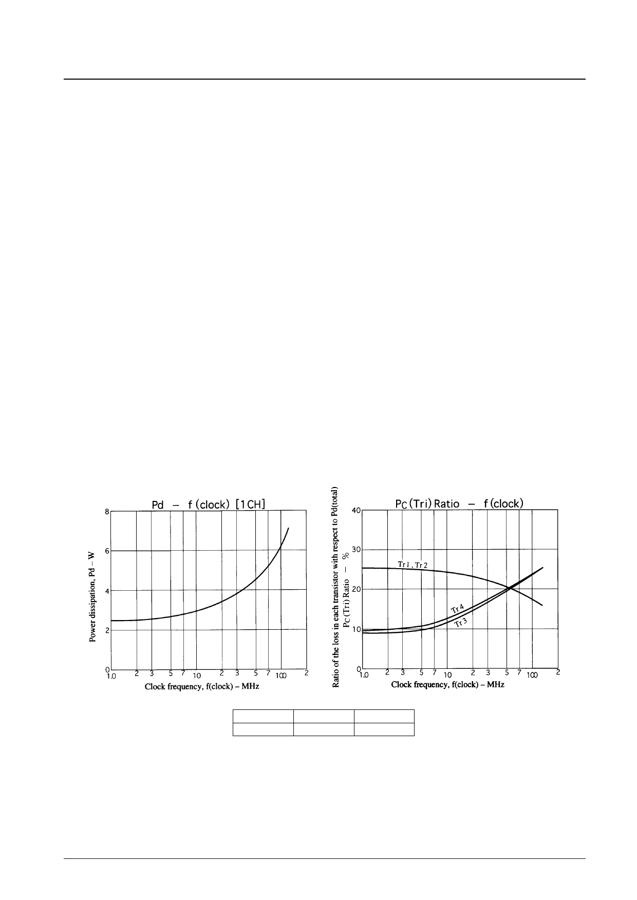
Equation (5) follows from deriving that value from the figure below and equation (3).
PC (Tr3, 4)f = 120 MHz = 6.9 × 0.25 ≈ 1.72 [W] ......................................................(5)
However, the actual usage conditions include a blanking period. If we calculate the power during this period
approximately at a 1-MHz power ratio, from Pd – f(clock) and PC (Tri)Ratio – f (clock) figures, we see that PC (BLK) for
transistors 3 and 4 will be:
PC BLK (Tr3, 4) = 2.6 × 0.08 = 0.21 [W].............................................................. (6)
If the blanking period is 20% of the total, from the data of equation (5) and formula (6) we see that the loss in transistors
3 and 4 will be:
PC (Tr3, 4) = PC (Tr3, 4) f = 120 MHz × 0.8 + PCBLK (Tr3, 4) × 0.2 ≈ 1.42 [W] ...(7)
Next, applying the value of θj–c to equation (7), shows ∆Tj to be:
∆Tj = 1.42 × 35 ≈ 50 [°C]
Since ∆Tj ≤ 50°C, it suffices to only consider the Tc ≤ 100°C condition in the thermal design. That is, in the thermal
design we design θh so that Tc will be under 100°C when Pd (total) = Pd (1ch) × 3 for the time when all three channels
are operating at their maximum levels.
∆Tc will be: ∆Tc = 100 – 60 = 40°C
θh = ∆Tc ÷ Pd (total) = 40 ÷ {(6.9 × 0.8 + 3.5 × 0.2) × 3} = 2.1
Thus:
θh = 2.1°C/W
In actual use, due to the actual ambient temperature, the operating conditions, and other factors, it will be possible to use
a heat sink smaller than the one required by the above design. Users should design an optimal heat sink using the data
presented above and their actual conditions.
VCC (V)
80
VOUT (V)
40
VO (center)
40
No. 5477-4/5
Share Link: 