M54HC193 View Datasheet(PDF) - STMicroelectronics
Part Name
Description
View to exact match
M54HC193
STMicroelectronics

M54HC193 Datasheet PDF : 15 Pages
| |||
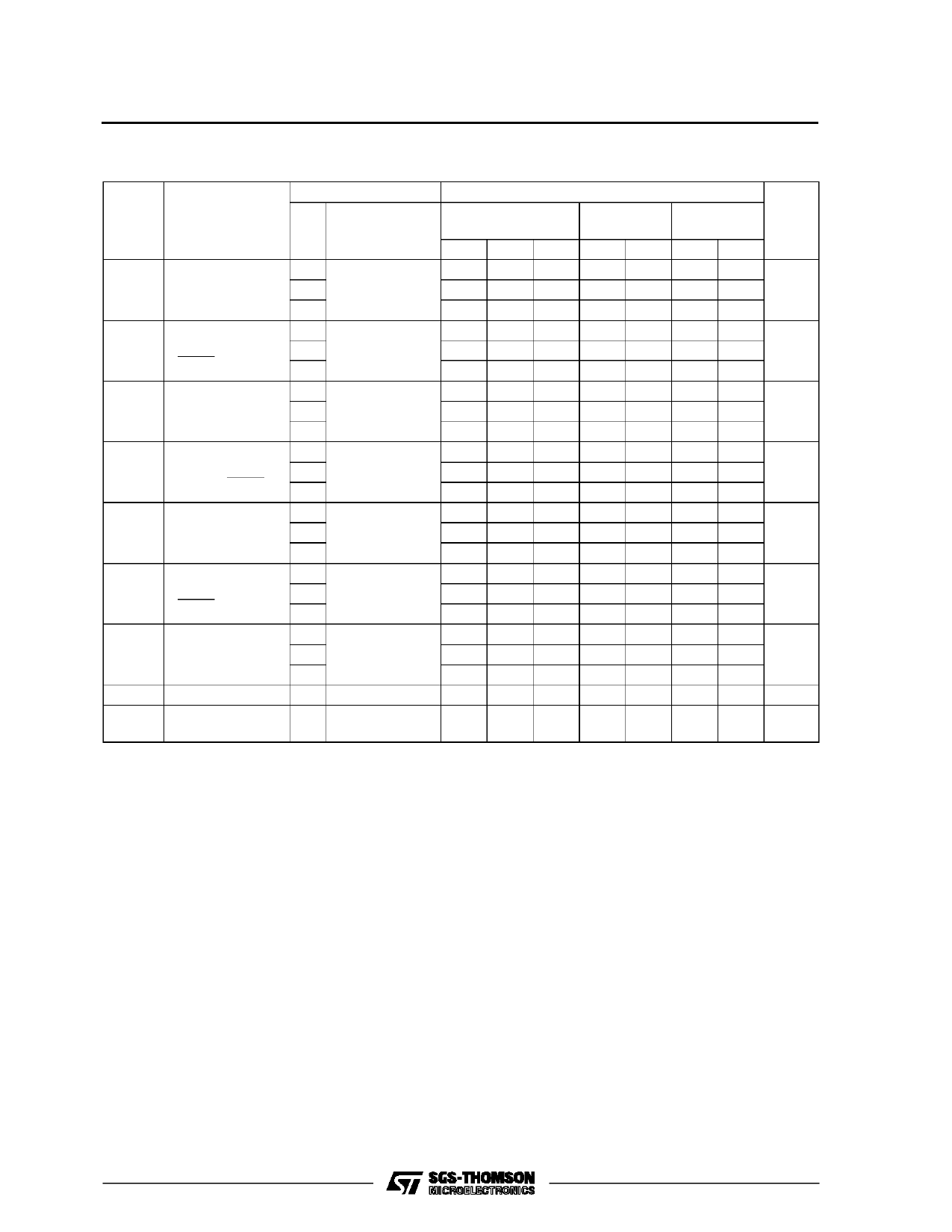
M54/M74HC192/193
AC ELECTRICAL CHARACTERISTICS (CL = 50 pF, Input tr = tf = 6 ns)
Symbol
Parameter
Test Conditions
VCC
(V)
TA = 25 oC
54HC and 74HC
Value
-40 to 85 oC -55 to 125 oC Unit
74HC
54HC
Min. Typ. Max. Min. Max. Min. Max.
tW(H) Minimum Pulse
2.0
tW(L) Width (COUNT
4.5
UP/DOWN)
6.0
34 100
125
150
9
20
25
30
ns
7
17
21
26
tW(L) Minimum Pulse 2.0
Width
4.5
(LOAD)
6.0
34 75
9
15
7
13
95
110
19
22
ns
16
19
tW(H) Minimum Pulse 2.0
Width
4.5
(CLEAR)
6.0
40 100
125
150
12 20
25
30
ns
10 17
21
26
ts
Minimum Set-up 2.0
Time
4.5
(DATA - LOAD) 6.0
30 75
9
15
7
13
95
110
19
22
ns
16
19
th
Minimum Hold
2.0
Time
4.5
0
0
0
0
0
0
ns
6.0
0
0
0
tREM Minimum
2.0
Removal Time
4.5
(LOAD)
6.0
6
50
65
75
2
10
13
15
ns
2
9
11
13
tREM Minimum
2.0
Removal Time
4.5
(CLEAR)
6.0
14 50
65
75
4
10
13
15
ns
3
9
11
13
CIN Input Capacitance
5
10
10
10 pF
CPD (*) Power Dissipation
for HC192
68
Capacitance
for HC193
67
pF
(*) CPD is defined as the value of the IC’s internal equivalent capacitance which is calculated from the operating current consumption without load.
(Refer to Test Circuit). Average operting current can be obtained by the following equation. ICC(opr) = CPD •VCC •fIN + ICC
9/15
Share Link: