S83C196KB View Datasheet(PDF) - Intel
Part Name
Description
View to exact match
S83C196KB Datasheet PDF : 22 Pages
| |||
8XC196KB 8XC196KB16
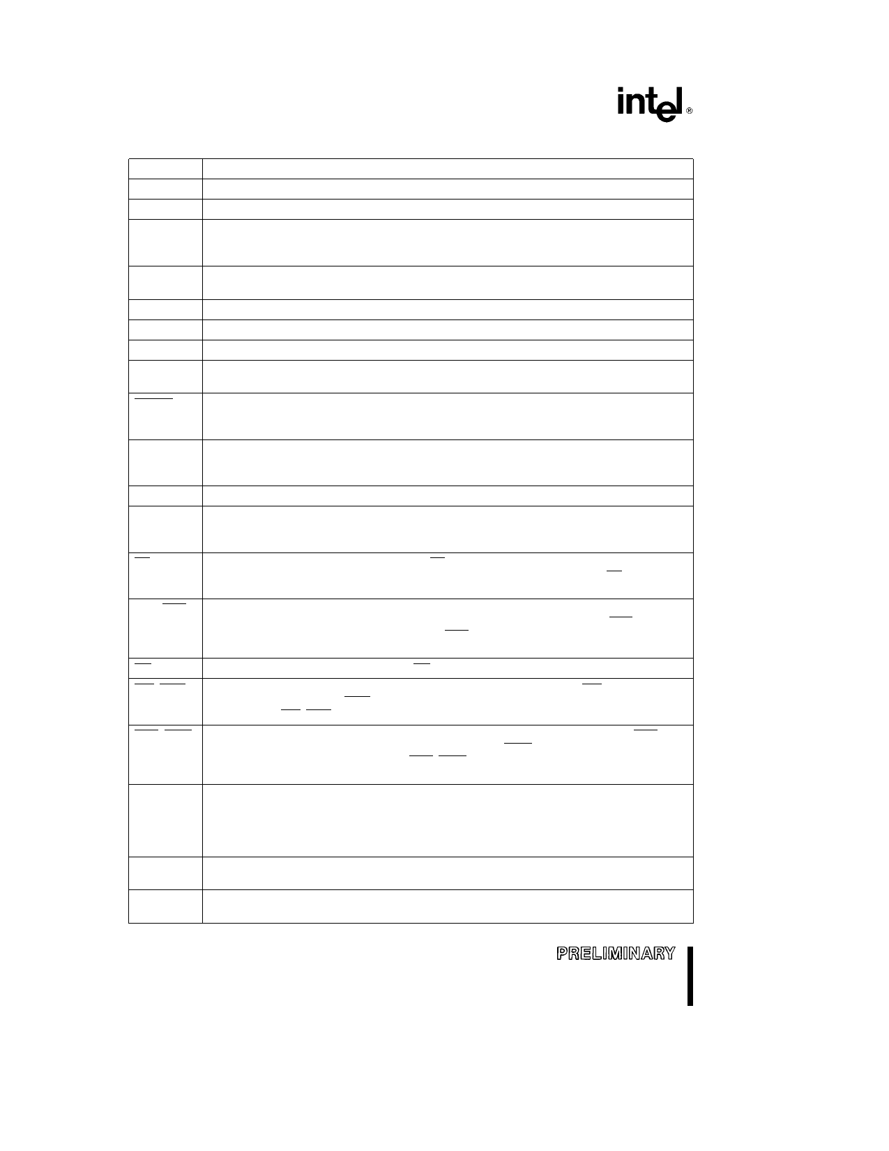
PIN DESCRIPTIONS
Symbol
Name and Function
VCC
VSS
VREF
Main supply voltage (5V)
Digital circuit ground (0V) There are multiple VSS pins all of them must be connected
Reference voltage for the A D converter (5V) VREF is also the supply voltage to the analog
portion of the A D converter and the logic used to read Port 0 Must be connected for A D
and Port 0 to function
ANGND
VPP
XTAL1
Reference ground for the A D converter Must be held at nominally the same potential as
VSS Connect VSS and ANGND at chip to avoid noise problems
Programming voltage Also timing pin for the return from power down circuit
Input of the oscillator inverter and of the internal clock generator
XTAL2
Output of the oscillator inverter
CLKOUT
Output of the internal clock generator The frequency of CLKOUT is the oscillator
frequency It has a 50% duty cycle
RESET
Reset input to and open-drain output from the chip Input low for at least 4 state times to reset
the chip The subsequent low-to-high transition re-synchronizes CLKOUT and commences a
10-state-time RESET sequence
BUSWIDTH Input for buswidth selection If CCR bit 1 is a one this pin selects the bus width for the bus
cycle in progress If BUSWIDTH is a 1 a 16-bit bus cycle occurs If BUSWIDTH is a 0 an 8-bit
cycle occurs If CCR bit 1 is a 0 the bus is always an 8-bit bus
NMI
A positive transition causes a vector through 203EH
INST
Output high during an external memory read indicates the read is an instruction fetch and
output low indicates a data fetch INST is valid throughout the bus cycle INST is activated
only during external memory accesses
EA
Input for memory select (External Access) EA equal to a TTL-high causes memory accesses
to locations 2000H through 3FFFH to be directed to on-chip ROM OTPROM EA equal to a
TTL-low causes accesses to these locations to be directed to off-chip memory
ALE ADV
Address Latch Enable or Address Valid output as selected by CCR Both pin options provide
a latch to demultiplex the address from the address data bus When the pin is ADV it goes
inactive high at the end of the bus cycle ALE ADV is activated only during external memory
accesses
RD
Read signal output to external memory RD is activated only during external memory reads
WR WRL
Write and Write Low output to external memory as selected by the CCR WR will go low for
every external write while WRL will go low only for external writes where an even byte is
being written WR WRL is activated only during external memory writes
BHE WRH
Bus High Enable or Write High output to external memory as selected by the CCR BHE will
go low for external writes to the high byte of the data bus WRH will go low for external writes
where an odd byte is being addressed BHE WRH is activated only during external memory
writes
READY
Ready input to lengthen external memory cycles If the pin is low prior to the falling edge of
CLKOUT the memory controller goes into a wait mode until the next positive transition in
CLKOUT occurs with READY high When the external memory is not being used READY has
no effect Internal control of the number of wait states inserted into a bus cycle (held not
ready) is available in the CCR
HSI
Inputs to High Speed Input Unit Four HSI pins are available HSI 0 HSI 1 HSI 2 and HSI 3
Two of them (HSI 2 and HSI 3) are shared with the HSO Unit
HSO
Outputs from High Speed Output Unit Six HSO pins are available HSO 0 HSO 1 HSO 2
HSO 3 HSO 4 and HSO 5 Two of them (HSO 4 and HSO 5) are shared with the HSI Unit
6
Share Link: 