VI-AIM View Datasheet(PDF) - Vicor
Part Name
Description
View to exact match
VI-AIM Datasheet PDF : 2 Pages
| |||
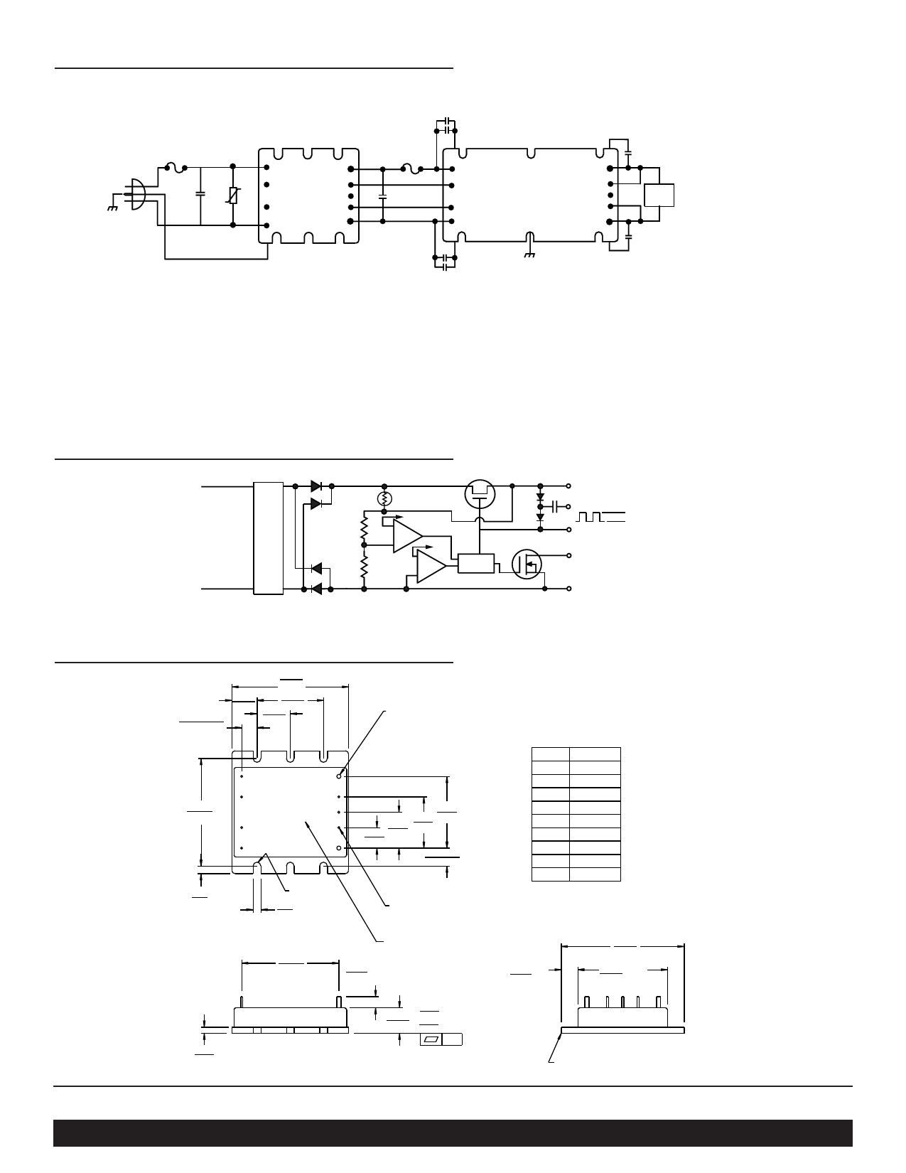
VI-AIM Connection Diagram, Typical Application
.01 µF (Two 4700 pF)
Y-Rated Capacitors
Universal
AC In
F1
.47 µF Z1
L1
N/C
N/C
L2/N
+Out
Gate In
Parallel
Gate Out
-Out
VI-AIM
F2
C out*
+In
Gate
In
Gate
Out
-In
VI-200/J00
Driver
+Out
+S
Trim
-S
-Out
.01 µF Ceramic
Load
.01 µF Ceramic
.01 µF (Two 4700 pF)
Y-Rated Capacitors
* See Vicor's Applications Manual, page 12-2, Selecting Capacitors for AIM Modules.
Z1: MOV P/N 03040
Fuse 1: 6.3A/250V (IEC 5X20 mm) Buss GDB-6.3 or 7A/250V (3AG 1/4" x 1 1/4") Littlefuse 314-007
Fuse 2: For VI-X7X-XX — Buss PC-Tron 2.5A (250V)
For VI-X6X-XX — Buss PC-Tron 3A (250V)
For VI-X5X-XX — Buss PC-Tron 5A
VI-AIM Block Diagram
L1
EMI
Filter
L2/N
Vref 1
U2
OV
Vref
2
OC
U1
+OUT
Q1 D2 C2
Gate Out
D1
10V
Parallel
Level
Shift
Gate In
Q2
-OUT
Mechanical Diagram
.30±.015
(7,6)±(0,38)
.49
(12,4)
2.28
(57,9)
1.30
(33,0)
.65
(16,5)
.080 Dia (2) places
Solder plate
over copper alloy
2.10
(53,4)
.15
(3,8)
4
9
3
8
VI-AIM 7
2
6
1
5
FULL R
.15
(3,8)
1.40
1.00 (35,6)
.70 (25,4)
.40 (17,8)
(10,2)
.35± .015
(8,9)±(0,38)
.040 (1,0) Dia (7) places
Solder plate
over copper alloy
Pin #
1
2
3
4
5
6
7
8
9
Function
L1
NC
NC
L2/N
+Out
Gate In
Parallel
Gate Out
–Out
1.90
(48,3)
Product ID
this surface
.22
(5,6) Min.
.30 Min.
(7,6)
2.40
(61,0)
1.75 Max.
(44,4)
.12
(3,0)
.50
(12,7)
+.030
(0,76)
-.000
(0)
.01
Aluminum Base
Vicor Corp. Tel: 800-735-6200, 978-470-2900 Fax: 978-475-6715 AIM, Universal AC Input Front End Module P/N 21924
Set your site on VICOR at www.vicorpower.com
Rev. 2.2 1/05/10M
Share Link: 