USP-500-12 View Datasheet(PDF) - Mean Well Enterprises Co., Ltd.
Part Name
Description
View to exact match
USP-500-12 Datasheet PDF : 4 Pages
| |||
500W Single Output with PFC Function
USP-500 series
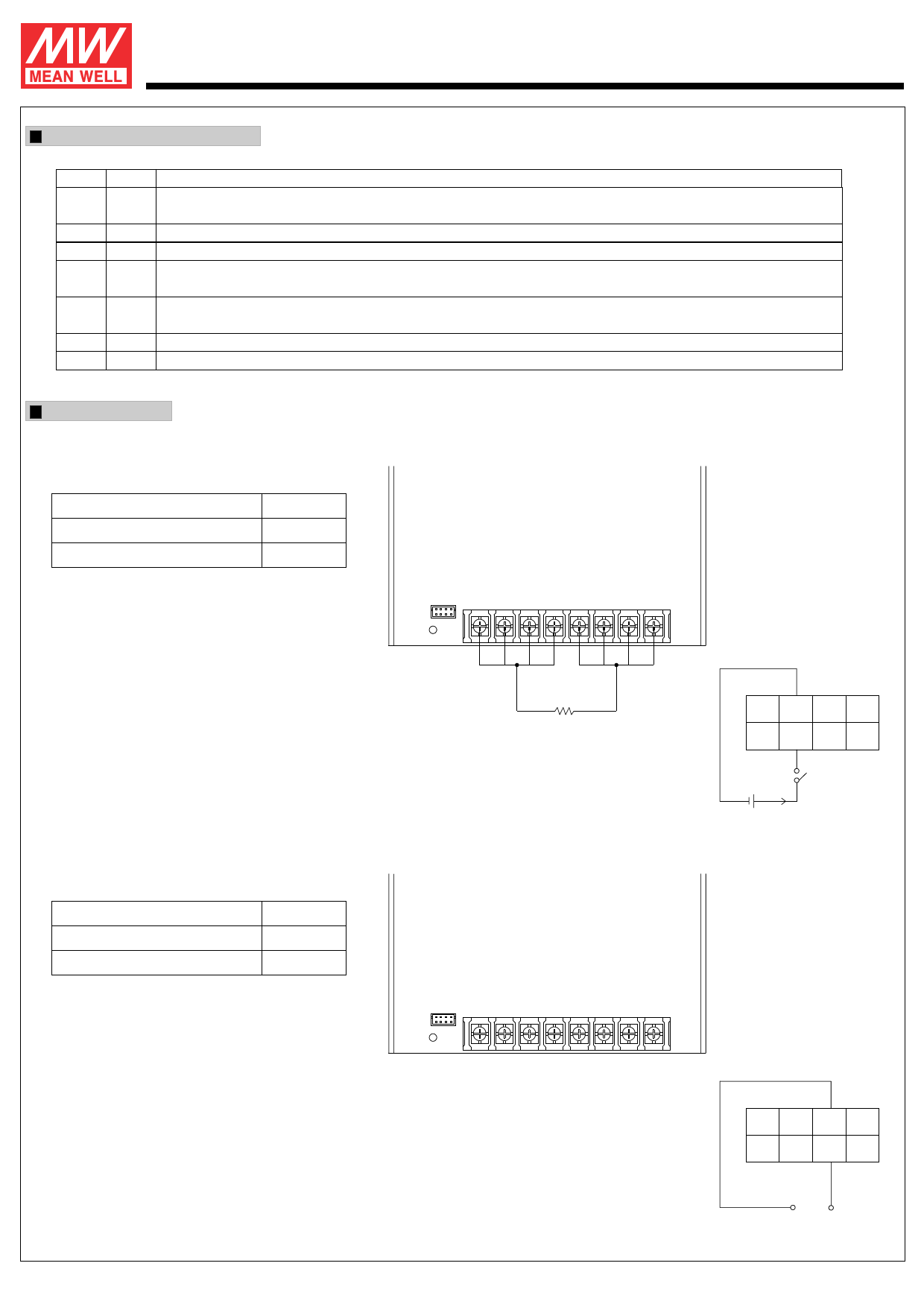
Function Description of CN50
Pin No. Function Description
1
+S
Positive sensing. The +S signal should be connected to the positive terminal of the load. The +S and -S leads should be twisted in pair to
minimize noise pick-up effect. The maximum line drop compensation is 0.5V.
2
GND This pin connects to the negative terminal (-V). Return for DC_OK signal output.
3
RC- Return for RC+ signal input.
4
CS Current sharing signal. When units are connected in parallel, the CS pins of the units should be connected to allow current balance
(Optional) between units.
5,8
-S
Negative sensing. The -S signal should be connected to the negative terminal of the load. The -S and +S leads should be twisted in pair to
minimize noise pick-up effect. The maximum line drop compensation is 0.5V.
6 DC-OK DC-OK signal is a TTL level signal, referenced to pin3(DC-OK GND). High when PSU turns on.
7
RC+ Turns the output on and off by electrical or dry contact between pin 7 ( RC+) and pin 3 (RC-). 0~0.8V: Power ON, 4~10V: Power OFF.
Function Manual
1.Remote Control
The PSU can be turned ON/OFF by using the
"Remote Control" function.
Between RC+(pin7) and RC-(pin3)
Output Status
SW OFF (0 ~ 0.8V)
ON
SW ON (4 ~ 10V)
OFF
CN50
4
8
1
5
LED
TB2
+V
-V
+-
LOAD
2.DC-OK Signal
DC-OK signal is a TTL level signal. High when PSU turns on.
Between DC-OK(pin6) and GND(pin2)
3.3 ~ 5.6V
0 ~ 1V
Output Status
ON
OFF
CN50
4
8
1
5
LED
Fig 1.1
TB2
+V
-V
4
CN50
1
NC RC- GND +S
-S RC+ DC-OK -S
8
5
SW
External Power
Source
I=6~20mA
Fig 2.1
4 CN50
1
NC RC- GND +S
-S RC+ DC-OK -S
8
5
File Name:USP-500-SPEC 2007-09-19
Share Link: 