M54HC195 View Datasheet(PDF) - STMicroelectronics
Part Name
Description
View to exact match
M54HC195 Datasheet PDF : 13 Pages
| |||
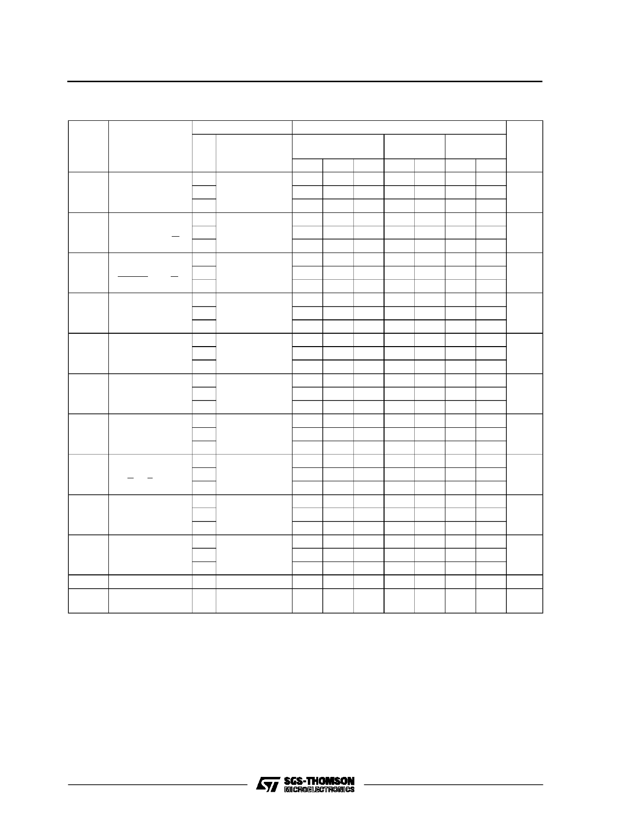
M54/M74HC195
AC ELECTRICAL CHARACTERISTICS (CL = 50 pF, Input tr = tf = 6 ns)
Symbol
Parameter
Test Conditions
VCC
(V)
TA = 25 oC
54HC and 74HC
Value
-40 to 85 oC -55 to 125 oC Unit
74HC
54HC
Min. Typ. Max. Min. Max. Min. Max.
tTLH Output Transition 2.0
tTHL Time
4.5
30 75
8
15
95
115
19
23
ns
6.0
7
13
16
20
tPLH Propagation
2.0
tPHL Delay Time
4.5
(CLOCK- Qn, QD) 6.0
48 125
155
190
16 25
31
38
ns
14 21
26
32
tPLH Propagation
2.0
tPHL Delay Time
4.5
(CLEAR- Qn, QD) 6.0
45 120
150
180
15 24
30
36
ns
13 20
26
31
fMAX Maximum Clock 2.0
Frequency
4.5
7.6 15
6
5
38 60
30
25
MHz
6.0
45 71
35
30
tW(H) Minimum Pulse 2.0
tW(L) Width
4.5
(CLOCK)
6.0
20 75
5
15
4
13
95
115
19
23
ns
16
20
tW(L) Minimum Pulse 2.0
Width
4.5
(CLEAR)
6.0
20 75
5
15
4
13
95
115
19
23
ns
16
20
ts
Minimum Set-up 2.0
Time
4.5
(PI)
6.0
28 75
7
15
6
13
95
115
19
23
ns
16
20
ts
Minimum Set-up 2.0
Time
4.5
(J, K, S/L)
6.0
28 75
7
15
6
13
95
115
19
23
ns
16
20
th
Minimum Hold
2.0
Time
4.5
0
0
0
0
0
0
ns
6.0
0
0
0
tREM Minimum
2.0
Removal Time
4.5
5
5
5
5
5
5
ns
6.0
5
5
5
CIN Input Capacitance
5
10
10
10 pF
CPD (*) Power Dissipation
72
Capacitance
pF
(*) CPD is defined as the value of the IC’s internal equivalent capacitance which is calculated from the operating current consumption without load.
(Refer to Test Circuit). Average operting current can be obtained by the following equation. ICC(opr) = CPD •VCC •fIN + ICC
7/13
Share Link: 