MI-AIM-M1 View Datasheet(PDF) - Vicor
Part Name
Description
View to exact match
MI-AIM-M1 Datasheet PDF : 2 Pages
| |||
Product Grade Specifications
PARAMETER
PRODUCT GRADE
I - Grade
M- Grade
Part Number
Storage temperature
Operating temperature (baseplate)
Power cycling burn-in
Temperature cycled with power off
17°C per minute rate of change
Test data supplied at these temperatures*
Warranty
Environmental compliance
MI-AIM-I1
-55°C to +125°C
-40°C to +100°C
12 hours, 25 cycles
12 cycles
-65°C to +100°C
-40°C, +80°C
2 years
MIL-STD-810
MI-AIM-M1
-65°C to +125°C
-55°C to +100°C
96 hours, 200 cycles
12 cycles
-65°C to +100°C
-55°C, +80°C
2 years
MIL-STD-810
*Test data available for review or download from vicorpower.com
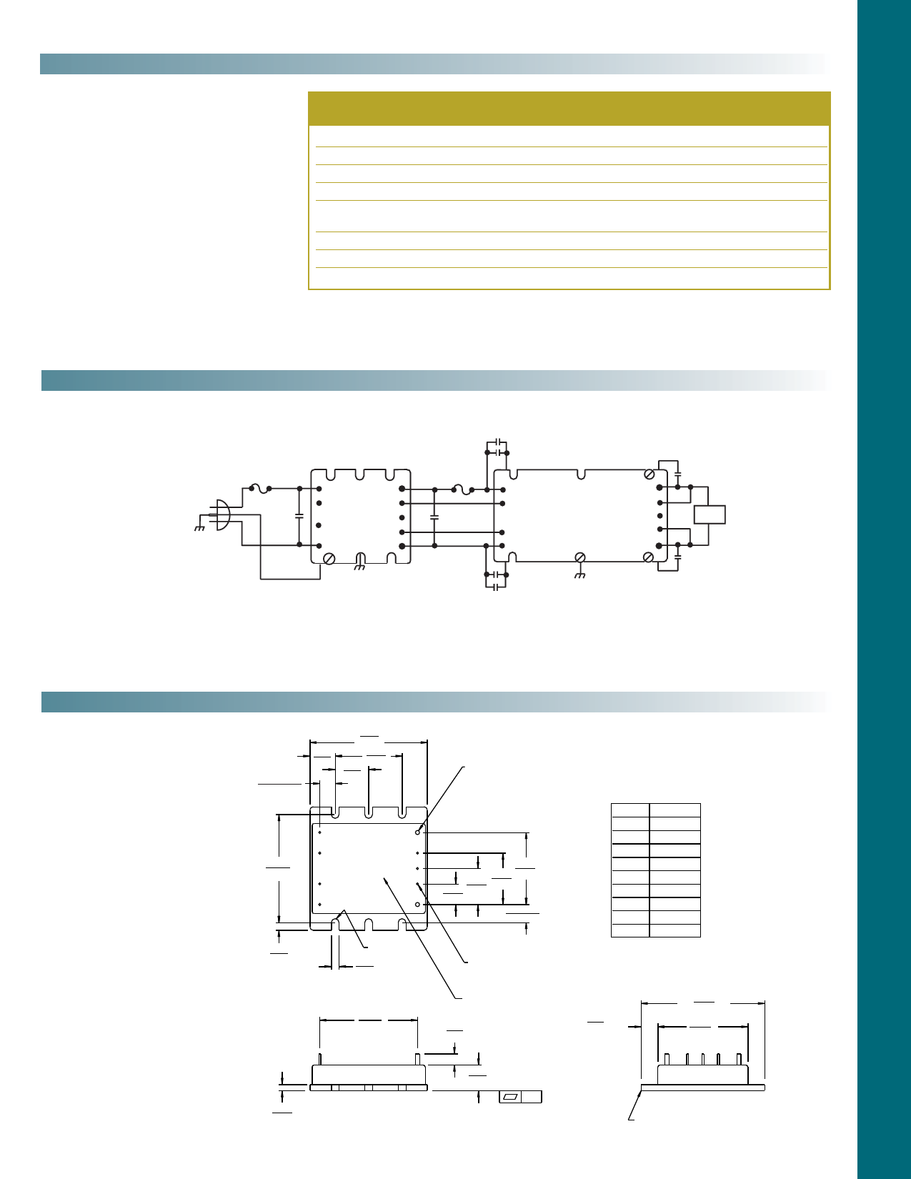
Connection Diagram
0.01 µF (Two 4700 pF )
Y-Rated Capacitors
AC In
F1
0.47 µF
L1
N/C
N/C
L2/N
+Out
Gate In
Parallel
Gate Out
-Out
F2
C out*
+In
Gate In
Gate Out
-In
MI-27x/J7x
Driver
+Out
+S
Trim
-S
-Out
0.01 µF Ceramic
Load
0.01 µF Ceramic
MI-AIM
0.01 µF (Two 4700 pF )
Y-Rated Capacitors
* 1200µF Max. (See Vicor's Applications Manual, page 12-2, Selecting Capacitors for AIM Modules.)
Fuse 1: 7A F03A type recommended.
Fuse 2: For MI-x7x-xx – Buss PC-Tron 2.5A (450V)
Mechanical Drawing
0.30±.015
(7,6)±(0,38)
0.49
(12,4)
2.28
(57,9)
1.30
(33,0)
0.65
(16,5)
2.10
(53,4)
4
9
3
8
MI-AIM 7
2
6
1
5
0.15
(3,8)
FULL R
0.15
(3,8)
1.90
(48,3)
0.080 Dia (2) places
Solder plate
over copper alloy
1.40
1.00 (35,6)
0.70 (25,4)
0.40 (17,8)
(10,2)
0.35± 0.015
(8,9)±(0,38)
Pin #
1
2
3
4
5
6
7
8
9
Function
L1
NC
NC
L2/N
+Out
Gate In
Parallel
Gate Out
–Out
0.040 (1,0) Dia (7) places
Solder plate
over copper alloy
Product ID
this surface
0.22
(5,6) Min.
0.30
(7,6) Min.
2.40
(61,0)
1.75
(44,4) Max.
0.12
(3,0)
0.50 +0.030 (0,76)
(12,7) -0.000 (0)
.01
Aluminum Base
MI-AIM 06/05 2 of 2
Share Link: 