CS52015-3GSTR3 View Datasheet(PDF) - Cherry semiconductor
Part Name
Description
View to exact match
CS52015-3GSTR3 Datasheet PDF : 6 Pages
| |||
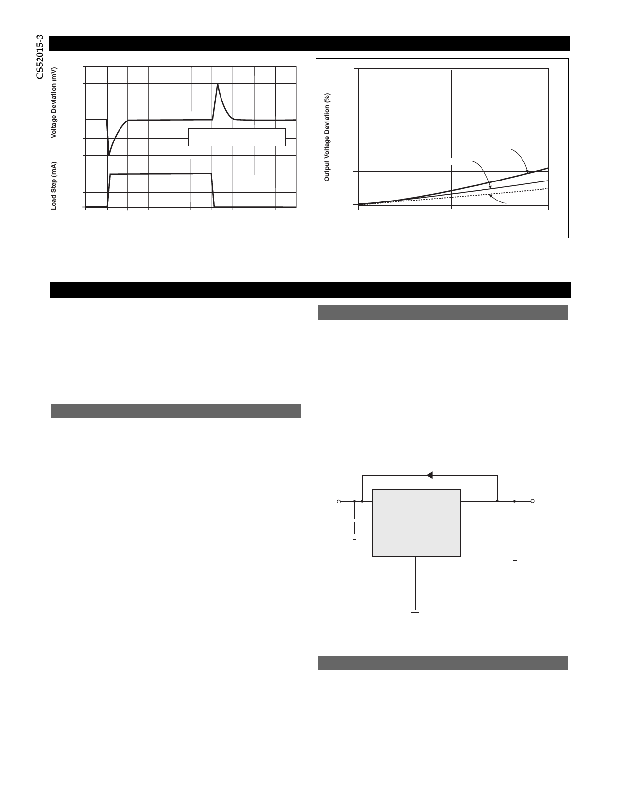
Typical Performance Characteristics
0.100
200
100
0
-100
COUT =CIN =22mF Tantalum
-200
1500
750
0
0
12
3
4
5
6
Time mS
7
8
9 10
0.075
0.050
0.025
0.000
0
TCASE = 25°C
TCASE = 125°C
1
Output Current (A)
TCASE = 0°C
2
Transient Response
Load Regulation vs. Output Current
Applications Information
The CS52015-3 linear regulator provides a 3.3V output
voltage at currents up to 1.5A. The regulator is protected
against overcurrent conditions and includes thermal
shutdown.
The CS52015-3 has a composite PNP-NPN output transistor
and requires an output capacitor for stability. A detailed
procedure for selecting this capacitor is included in the
Stability Considerations section.
Stability Considerations
The output or compensation capacitor helps determine
three main characteristics of a linear regulator: start-up
delay, load transient response and loop stability.
The capacitor value and type are based on cost, availabili-
ty, size and temperature constraints. A tantalum or alu-
minum electrolytic capacitor is best, since a film or ceramic
capacitor with almost zero ESR can cause instability. The
aluminum electrolytic capacitor is the least expensive solu-
tion. However, when the circuit operates at low tempera-
tures, both the value and ESR of the capacitor will vary
considerably. The capacitor manufacturersÕ data sheet pro-
vides this information.
A 22µF tantalum capacitor will work for most applications,
but with high current regulators such as the CS52015-3 the
transient response and stability improve with higher val-
ues of capacitance. The majority of applications for this
regulator involve large changes in load current so the out-
put capacitor must supply the instantaneous load current.
The ESR of the output capacitor causes an immediate drop
in output voltage given by:
ÆV = ÆI ´ ESR
For microprocessor applications it is customary to use an
output capacitor network consisting of several tantalum and
ceramic capacitors in parallel. This reduces the overall ESR
and reduces the instantaneous output voltage drop under
load transient conditions. The output capacitor network
should be as close as possible to the load for the best results.
Protection Diodes
When large external capacitors are used with a linear regu-
lator it is sometimes necessary to add protection diodes. If
the input voltage of the regulator gets shorted, the output
capacitor will discharge into the output of the regulator.
The discharge current depends on the value of the capaci-
tor, the output voltage and the rate at which VIN drops. In
the CS52015-3 linear regulator, the discharge path is
through a large junction and protection diodes are not usu-
ally needed. If the regulator is used with large values of
output capacitance and the input voltage is instantaneous-
ly shorted to ground, damage can occur. In this case, a
diode connected as shown in Figure 1 is recommended.
VIN
C1
IN4002 (optional)
VIN
VOUT
CS52015-3
Gnd
VOUT
C2
Figure 1: Protection diode scheme for large output capacitors.
Output Voltage Sensing
Since the CS52015-3 is a three terminal regulator, it is not
possible to provide true remote load sensing. Load regula-
tion is limited by the resistance of the conductors connect-
ing the regulator to the load. For best results the regulator
should be connected as shown in Figure 2.
4
Share Link: 