HA16117 View Datasheet(PDF) - Hitachi -> Renesas Electronics
Part Name
Description
View to exact match
HA16117 Datasheet PDF : 31 Pages
| |||
HA16117F Series
Internal Operation and Usage Notes
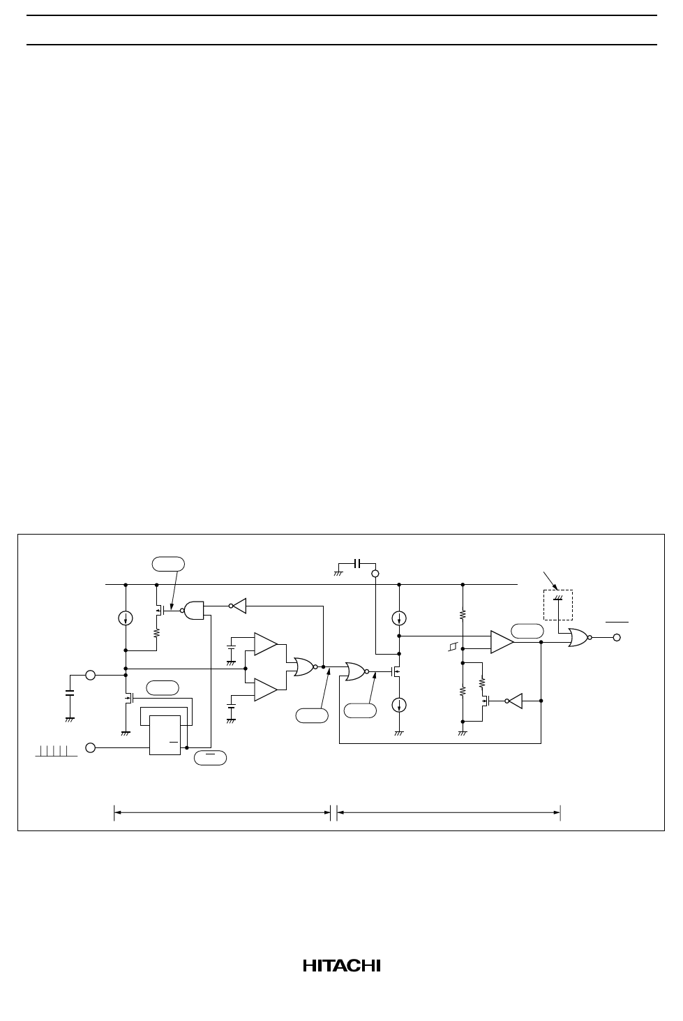
Figure 3 shows an equivalent circuit of the watchdog timer block with a VCC pin level of 5 V and ACC pin
level of 0 V, and the following pages show internal operation timing charts for different P-RUN
frequencies. (Descriptions apply to conditions CF = 0.01 µF, CR = 0.1 µF, R2/(R1 + R2) = 0.6.)
Operation
The power-on and auto-reset circuit is a multivibrator with timing controlled by CR charge current I1 and
discharge current I2. As I1 : I2 ≈ 3 : 1 (Typ design value), when the (WD) (watchdog filter circuit output)
on-duty is 25% or above, the CR pin potential does not fall below 1.6 V. Therefore, (C) in the figure below
is fixed low, and RES is not output. The (WD) on-duty varies according to the P-RUN frequency. If the
frequency is lower or higher than the design value, the (WD) on-duty decreases, and at 25% or below, RES
is output. Refer to the timing charts on the following pages for an explanation of the operation of the
watchdog filter.
Usage Notes
• When the P-RUN frequency reaches 20 kHz or above, tOFF is short (see the timing charts on the
following pages). This must be borne in mind in the design stage.
• If the P-RUN frequency fluctuates, RES may also be output within the normal detection set frequency
(see the timing charts on the following pages).
• Detection frequencies fH and fL described in the Data Book are Typ values, and a certain amount of
dispersion can be expected. A margin of ±30% or more should be allowed for in the design.
Iw
0.8 µ
typ
CF
0.01 µ
P-RUN
A
VCC (5 V)
3.6 V
−
+
Q
0.9 V −
+
WD
DQ
φQ
1/2
Q
frequency divider
Watchdog filter circuit
0.1 µ
CR
I1
8 µ typ
3.2 V
1.6 V
I2
B
10.7 µ
typ
Low voltage detection block
−
C
+
RES
Power-on and auto-reset circuit
Figure 3 Watchdog Timer Evaliation Circuit
7
Share Link: 