G9205 View Datasheet(PDF) - Hamamatsu Photonics
Part Name
Description
View to exact match
G9205 Datasheet PDF : 6 Pages
| |||
InGaAs linear image sensors
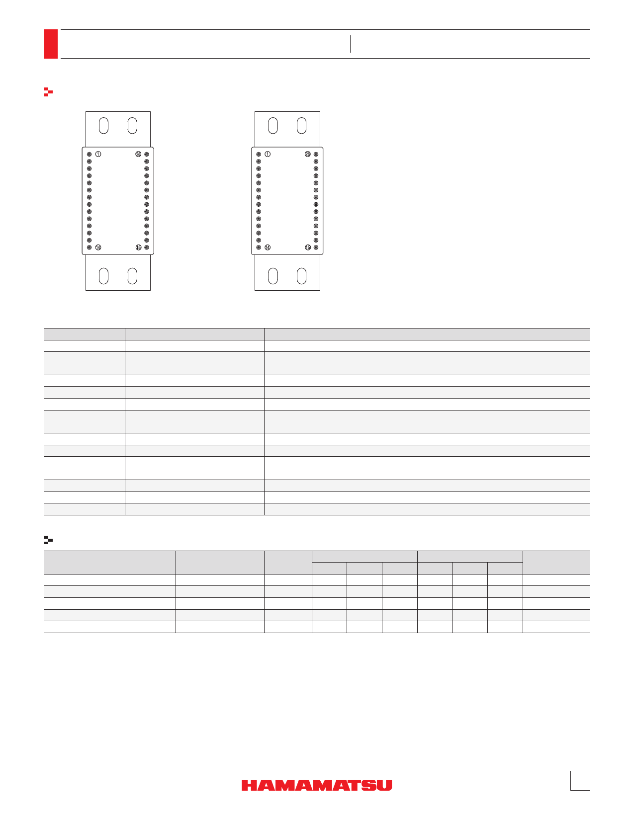
Pin connection (top view)
256 PIXELS
512 PIXELS
G9211 to G9214/G9205 to G9208 Series
TE +
THERM
THERM
CASE
Cf SELECT
RESET
TE -
AD-TRIG
Vdd
Vss
INP
CLK
Vref
VIDEO
RESET-EVEN
TE +
AD-TRIG-EVEN
THERM
THERM
CASE
CLK-EVEN
VIDEO-EVEN
Cf SELECT
RESET-ODD
TE -
AD-TRIG-ODD
Vdd
Vss
INP
CLK-ODD
Vref
VIDEO-ODD
KMIRC0013EA
Terminal name
CLK
RESET
Vdd
Vss
INP
Cf SELECT
CASE
THERM
TE+, TE-
AD-TRIG
VIDEO
Vref
Input/Output
Input (CMOS logic compatible)
Input (CMOS logic compatible)
Input
Input
Input
Input
-
Output
Input
Output
Output
Input
Function and recommended connection
Clock pulse for operating the CMOS shift register
Reset pulse for initializing the feedback capacitance in the charge amplifier formed
in the CMOS chip. The width of the reset pulse is integration time.
Supply voltage for operating the signal processing circuit in the CMOS chip
Ground for the signal processing circuit in the CMOS chip
Reset voltage for the charge amplifier array in the CMOS chip
Voltage that determines the conversion efficiency in the CMOS chip. Low gain
(CE=16 nV/e-) at 0 V, and high gain (CE=320 nV/e-) at 5 V.
This terminal is electrically connected to the package.
Thermistor for monitoring temperature inside the package
Power supply terminal for the thermoelectric cooler that cools the photodiode
array. No connection for room temperature operation type.
Digital signal for AD conversion; positive polarity
Analog video signal; positive polarity
Reset voltage for the offset compensation circuit in the CMOS chip
Specifications of TE-cooler (Ta=25 °C, Vdd=5 V, INP=4.5 V)
Parameter
One-stage TE-cooler
Two-stage TE-cooler
Condition
Symbol Min. Typ. Max. Min. Typ. Max.
Unit
TE-cooler allowable current
Ic Max.
-
-
1.8
-
-
2.8
A
TE-cooler allowable voltage
Temperature difference *6
*7
Thermistor resistance
Vc Max.
-
-
5.0
-
-
4.0
V
Δt
40
-
-
50
-
-
°C
Rth
4.85 5.00 5.15 4.85 5.00 5.15
kΩ
Thermistor power dissipation
Pth
-
-
0.2
-
-
0.2
mW
*6: This is a temperature difference between the surface of active area and the heat radiating portion of package.
*7: One-stage thermoelectrically cooled type: Ic=1.4 A, two-stage thermoelectrically cooled type: Ic=2.6 A.
5
Share Link: 