FX5-20P-SH View Datasheet(PDF) - HIROSE ELECTRIC
Part Name
Description
View to exact match
FX5-20P-SH Datasheet PDF : 7 Pages
| |||
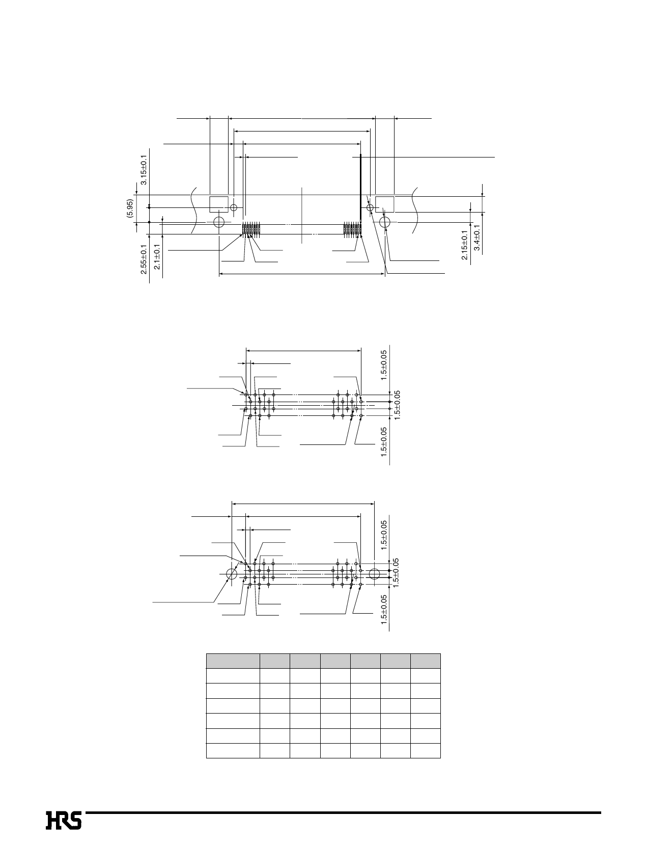
BPCB mounting pattern
qHeader
FX5-*-SH, FX5-*-SH3
4±0.1
2.05±0.05
A ±0.1
B ±0.05
C ±0.05
0.5±0.02
(Mating side)
4±0.1
0.3±0.03 (Land pattern)
0.25±0.03 (Metal mask)
a1
(Polarity mark position) b1
b2
a2
D±0.1
a*
b*
qReceptacle
FX5-*S2A-DSA
E ±0.1
1±0.05
a2
a3
a*
a1
a4
(Polarity mark position)
2-Ø2.3
+0.1
0
2-Ø1.4±0.05
* = (number of contacts)/2
b1
b4
b2
b3
Ø0.6
+0.1
0
b*
FX5-*S2A-DSAL
3±0.05
a2
a1
(Polarity mark position)
F ±0.1
E ±0.1
1±0.05
a3
a*
a4
* = (number of contacts)/2
2-Ø2.3
+0.1
0
b1
b4
b2
b3
Ø0.6
+0.1
0
b*
* = (number of contacts)/2
Number of Contacts A
B
C
D
20
16 13.6 9.5 20
40
26 23.6 19.5 30
52
32 29.6 25.5 36
56
34 31.6 27.5 38
68
40 37.6 33.5 44
80
46 43.6 39.5 50
Unit: mm
E
F
9 15
19 25
25 31
27 33
33 39
39 45
Note: If the connector is installed in the board beyond the above recommended size, it may cause the connector to board mounting failure
or the soldering failure. It is desirable to implement the board process on the recommended PCB mounting pattern.
A210
Share Link: 