CS51411 View Datasheet(PDF) - ON Semiconductor
Part Name
Description
View to exact match
CS51411 Datasheet PDF : 20 Pages
| |||
CS51411, CS51412, CS51413, CS51414
PRODUCT SELECTION GUIDE
Part Number
CS51411E
CS51411G
CS51412E
CS51412G
CS51413E
CS51413G
CS51414E
CS51414G
Frequency
260 kHz
260 kHz
260 kHz
260 kHz
520 kHz
520 kHz
520 kHz
520 kHz
Temperature Range
-40°C to 85°C
0°C to 70°C
-40°C to 85°C
0°C to 70°C
-40°C to 85°C
0°C to 70°C
-40°C to 85°C
0°C to 70°C
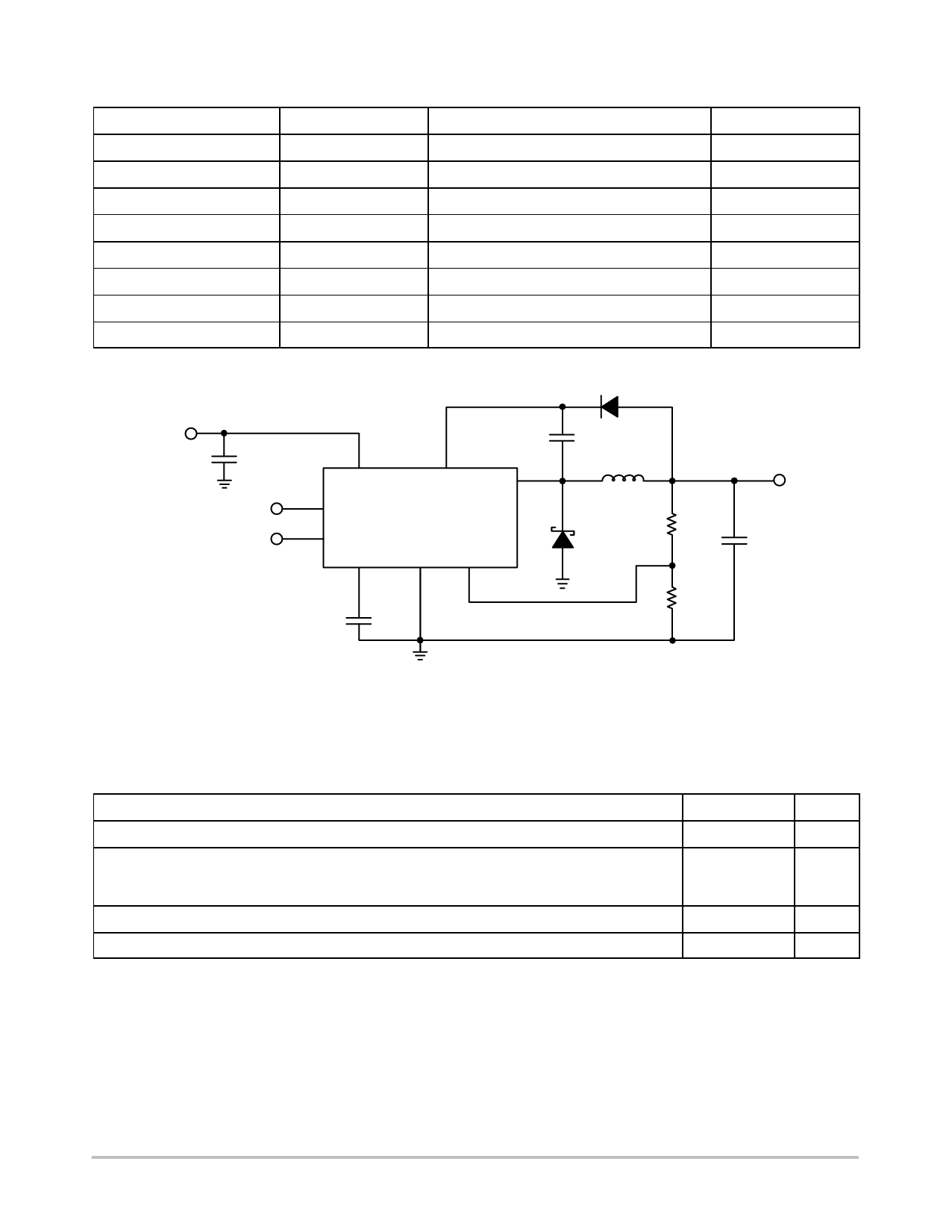
4.5 V - 16 V
C2
100 mF
Shutdown
SYNC
U1 2
VIN
4
SHDNB
5
SYNC
VC
8
1
BOOST
3
VSW
CS51411/3
GND VFB
6
7
C4
0.1 mF
D1 1N4148
C1
0.1 mF
L1
15 mH
R1
D3
205
1N5821
R2
127
Bias/Sync
Sync
Sync
Bias
Bias
Sync
Sync
Bias
Bias
3.3 V
C3
100 mF
Figure 1. Application Diagram, 4.5 V - 16 V to 3.3 V @ 1.0 A Converter
MAXIMUM RATINGS
Rating
Value
Unit
Operating Junction Temperature Range, TJ
Lead Temperature Soldering:
-40 to 150
°C
Reflow for Leaded: (SMD styles only) (Note 1)
230 peak
Reflow for Pb-Free: (SMD styles only) (Note 2)
260 peak
°C
(Note 3)
Storage Temperature Range, TS
-65 to +150
°C
ESD Damage Threshold (Human Body Model)
2.0
kV
Stresses exceeding Maximum Ratings may damage the device. Maximum Ratings are stress ratings only. Functional operation above the
Recommended Operating Conditions is not implied. Extended exposure to stresses above the Recommended Operating Conditions may affect
device reliability.
1. 60-150 second above 183°C, 30 second maximum at peak.
2. 60-150 second above 217°C, 40 second maximum at peak.
3. +5°C/0°C allowable conditions, applies to both Pb and Pb-Free Devices.
http://onsemi.com
3
Share Link: 