AT27BV512-90TI View Datasheet(PDF) - Atmel Corporation
Part Name
Description
View to exact match
AT27BV512-90TI
Atmel Corporation

AT27BV512-90TI Datasheet PDF : 9 Pages
| |||
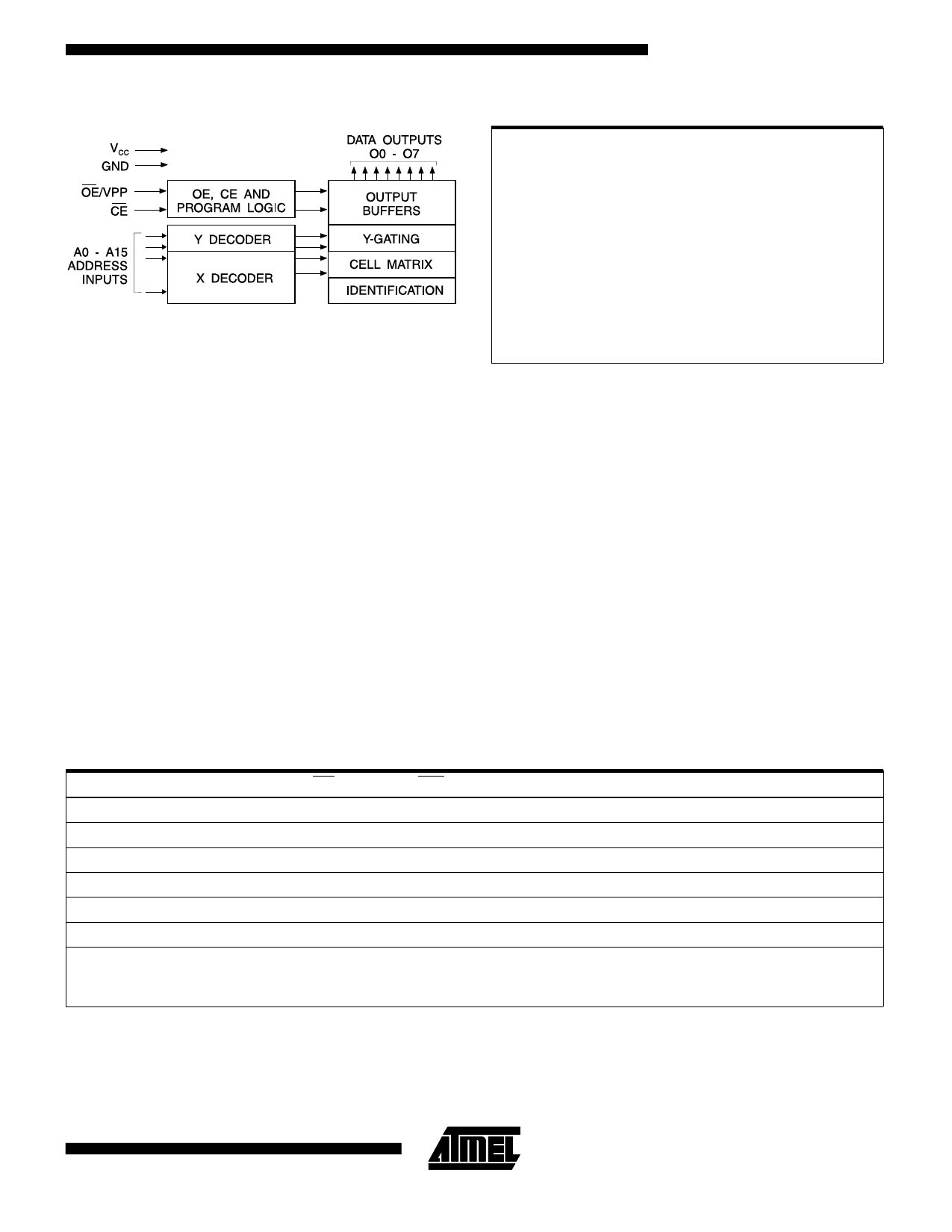
Block Diagram
AT27BV512
Absolute Maximum Ratings*
Temperature Under Bias .................. -40°C to +85°C
Storage Temperature...................... -65°C to +125°C
Voltage on Any Pin with
Respect to Ground......................... -2.0V to +7.0V (1)
Voltage on A9 with
Respect to Ground ...................... -2.0V to +14.0V (1)
VPP Supply Voltage with
Respect to Ground....................... -2.0V to +14.0V (1)
*NOTICE: Stresses beyond those listed under “Absolute Maxi-
mum Ratings” may cause permanent damage to the device.
This is a stress rating only and functional operation of the
device at these or any other conditions beyond those indi-
cated in the operational sections of this specification is not
implied. Exposure to absolute maximum rating conditions
for extended periods may affect device reliability.
Note:
1. Minimum voltage is -0.6V dc which may undershoot
to -2.0V for pulses of less than 20 ns. Maximum out-
put pin voltage is VCC + 0.75V dc which may be ex-
ceeded if certain precautions are observed (consult
application notes) and which may overshoot to
+7.0V for pulses of less than 20 ns.
Operating Modes
Mode \ Pin
CE
Read (2)
VIL
Output Disable (2)
VIL
Standby (2)
VIH
Rapid Program (3)
VIL
PGM Verify (3)
VIL
PGM Inhibit (3)
VIH
Product Identification (3, 5)
VIL
OE/VPP
VIL
VIH
X
VPP
VIL
VPP
VIL
Ai
Ai
X (1)
X
Ai
Ai
X
A9 = VH (4)
A0 = VIH or VIL
A1 - A15 = VIL
VCC
VCC (2)
VCC (2)
VCC (2)
VCC (3)
VCC (3)
VCC (3)
VCC (3)
Outputs
DOUT
High Z
High Z
DIN
DOUT
High Z
Identification
Code
Notes: 1. X can be VIL or VIH.
2. Read, output disable, and standby modes require,
2.7V ≤ VCC ≤ 3.6V, or 4.5V ≤ VCC ≤ 5.5V.
3. Refer to Programming Characteristics.
Programming modes require VCC = 6.5V.
4. VH = 12.0 ± 0.5V.
5. Two identifier bytes may be selected. All Ai inputs are held
low (VIL), except A9 which is set to VH and A0 which is tog-
gled low (VIL) to select the Manufacturer’s Identification byte
and high (VIH) to select the Device Code byte.
3-15
Share Link: