A1373 View Datasheet(PDF) - Allegro MicroSystems
Part Name
Description
View to exact match
A1373 Datasheet PDF : 22 Pages
| |||
A1373 and
A1374
High Precision, Output Pin Programmable
Linear Hall Effect Sensors
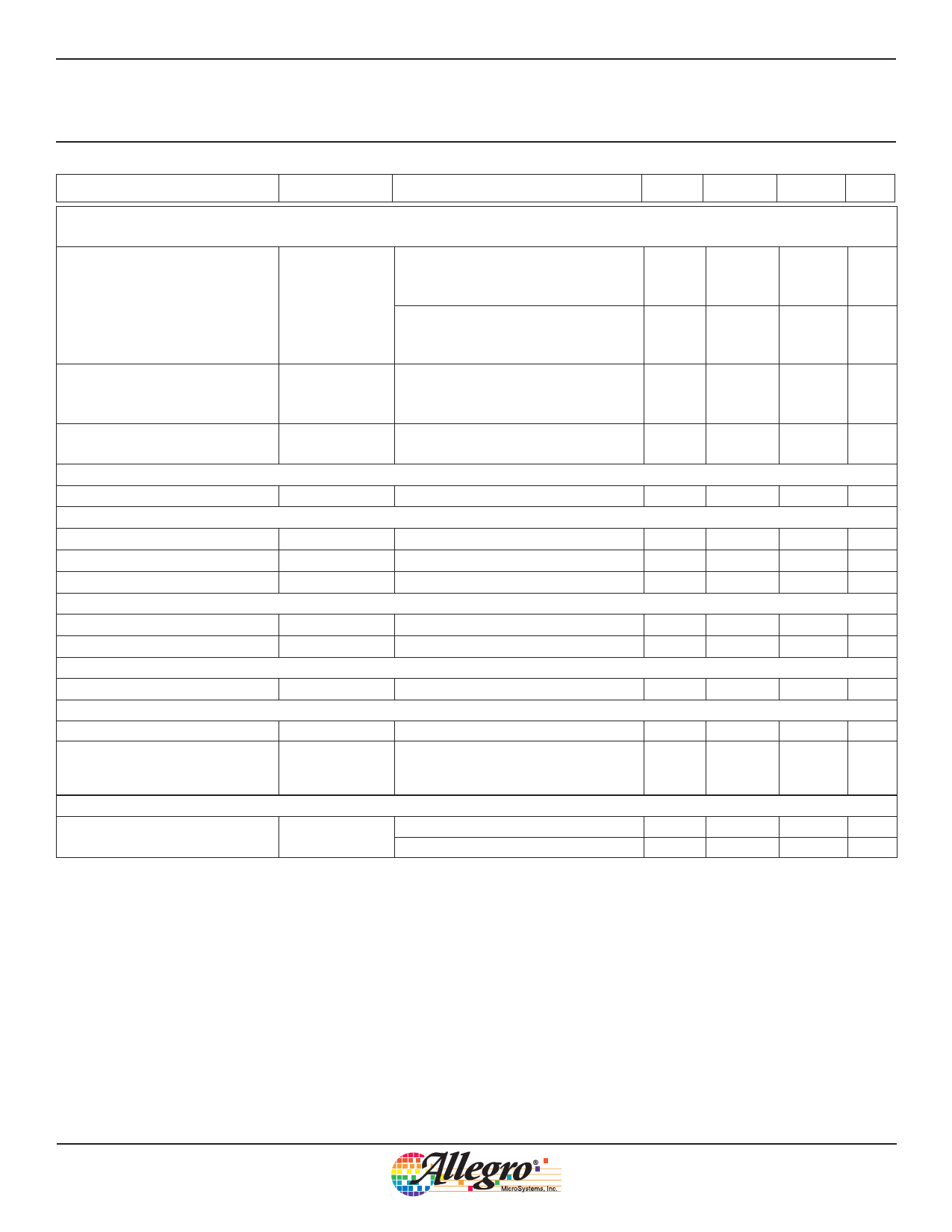
CHARACTERISTIC PARAMETERS (continued)
Characteristic
Symbol
Test Conditions
Min.
Typ.
Max Units
SENSITIVITY TEMPERATURE COEFFICIENT PROGRAMMING over operating temperature range, VCC= 5.0 V, unless
otherwise noted
Sensitivity Temperature
Coefficient Range
Sensitivity T/C codes 0 to 11,
minimum (absolute) positive
–
0.07
– %/°C
temperature coefficient attainable
TC
Sensitivity T/C codes 16 to 27,
minimum (absolute) negative
–
–0.016
– %/°C
temperature coefficient attainable
Average Sensitivity
Temperature Coefficient Step
Size4,5,6
StepTC
TA = 150°C
–
0.01
– %/°C
Sensitivity Temperature
Coefficient Programming Bits
–
–
5
–
Bit
ONE-TIME PROGRAMMING
Device Programming Lock Bit
–
–
1
–
Bit
RATIOMETRY over operating temperature range, VCC= 5.0 V, unless otherwise noted
Quiescent Voltage Error
RatVOUT(Q) VCC at VOPERATING
–
±0.25
–
%
Sensitivity Error
RatSENS
VCC at VOPERATING
–
±1.0
–
%
Clamp Error
RatVOUTCLP VCC at VOPERATING
–
±1.5
–
%
LINEARITY over operating temperature range, VCC= 5.0 V, unless otherwise noted
Positive Linearity Error
Lin+
VCC at VOPERATING
–
±0.5
–
%
Negative Linearity Error
Lin–
VCC at VOPERATING
–
±0.5
–
%
SYMMETRY over operating temperature range, VCC= 5.0 V, unless otherwise noted
Symmetry Error
Sym
VCC at VOPERATING – VCC
–
±0.35
–
%
ADDITIONAL CHARACTERISTICS
Sensitivity Drift9
ΔSens
–
–
±2
%
Package Thermal Resistance
1 layer PCB with copper limited to
RθJA
solder pads; see Allegro web site for
–
177
additional thermal information
–
°C/W
FAULT CONDITIONS over operating temperature range, VCC= 5.0 V, unless otherwise noted
Shorted Output Wire
IOUTSHT
VOUT pin to VCC pin
VOUT pin to GND pin
–
–
18
mA
–
–
4
mA
1 tPO does not include tCLP , specified in the Quiescent Programming section of this table.
2 Peak to peak value exceeded: 0.3% (6σ).
3 For A1373, no digital noise is present at the output.
4 Step size is larger than required for the specified range, to take into account manufacturing spread.
5 Individual code step sizes can be greater than 2× larger than the step size at each significant bit rollover.
6 Average fine code step size in a given range = (Output value at highest fine code in the range – Output value at code 0 of the range) / Total quantity of
steps (codes) in the range.
7 Values indicated are valid if any additional magnetic field does not exceed B(kG)= ±2 (V) / Sens (mv/G), after VOUTCLP is reached.
8 Program the Sensitivity T/C register before programming Sensitivity Coarse and Sensitivity Fine, due to a worst case shift of ±3% in sensitivity at 25°C
at the maximum values for Sensitivity T/C: Positive T/C and Sensitivity T/C: Negative T/C. The Programming Guidelines section in this document lists a
complete recommended order for programming individual values.
9Drift due to temperature cycling is due to package effects on the Hall transducer. The stress is reduced when the package is baked. However, it will
recover over time after removal from the bake.
Allegro MicroSystems, Inc.
5
115 Northeast Cutoff, Box 15036
Worcester, Massachusetts 01615-0036 (508) 853-5000
www.allegromicro.com
Share Link: 