74LVQ299(2004) View Datasheet(PDF) - STMicroelectronics
Part Name
Description
View to exact match
74LVQ299 Datasheet PDF : 15 Pages
| |||
74LVQ299
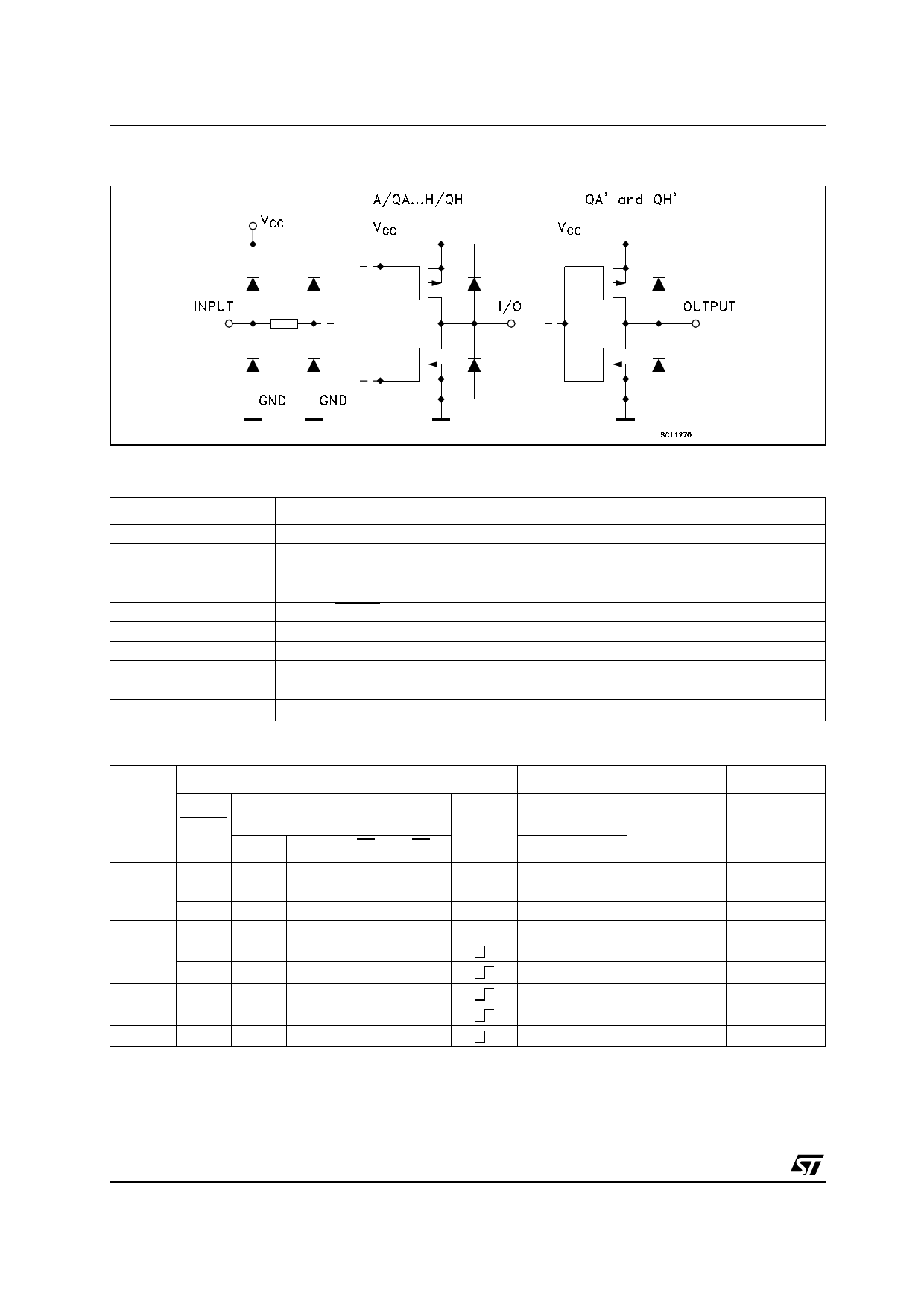
Figure 2: Input And Output Equivalent Circuit
Table 2: Pin Description
PIN N°
1, 19
2, 3
7, 13, 6, 14, 5, 15, 4, 16
8, 17
9
11
12
18
10
20
Table 3: Truth Table
SYMBOL
S0, S1
G1, G2
A/QA to H/QH
QA’,QH’
CLEAR
SR
CLOCK
SL
GND
VCC
NAME AND FUNCTION
Mode Select Inputs
3-State Output Enable Inputs (Active LOW)
Parallel Data Inputs or 3-State Parallel Outputs (Bus Driver)
Serial Outputs (Standard Output)
Asynchronous Master Reset Input (Active LOW)
Serial Data Shift Right Input
Clock Input (LOW to HIGH, Edge-triggered)
Serial Data Shift Left Input
Ground (0V)
Positive Supply Voltage
MODE
CLEAR
Z
L
L
CLEAR
L
HOLD
H
SHIFT
H
RIGHT
H
SHIFT
H
LEFT
H
LOAD
H
INPUTS
FUNCTION
SELECTED
OUTPUT
CONTROL
S1
S0
G1* G2*
H
H
X
X
L
X
L
L
X
L
L
L
L
L
L
L
L
H
L
L
L
H
L
L
H
L
L
L
H
L
L
L
H
H
X
X
CLOCK
X
X
X
X
INPUTS/OUTPUTS
OUTPUTS
SERIAL
SL
SR
X
X
X
X
X
X
X
X
X
H
X
L
H
X
L
X
X
X
A/QA H/QH QA’ QH’
Z
L
L
QA0
H
L
QBn
QBn
a
Z
L
L
QH0
QGn
QGn
H
L
h
L
L
L
QA0
H
L
QBn
QBn
a
L
L
L
QH0
QGn
QGn
H
L
h
* When one or both controls are high, the eight input/output terminals are the high impedance state: however sequential operation or cleaning
of the register is not affected.
Z: High Impedance
Qn0: The level of An before the indicated steady state input conditions were established.
Qnn: The level of Qn before the most recent active transition indicated by OR
a, h: The level of the steady state inputs A, H, respectively.
X: Don’t Care
2/15
Share Link: 