4-5435166-9 View Datasheet(PDF) - Tyco Electronics
Part Name
Description
View to exact match
4-5435166-9 Datasheet PDF : 4 Pages
| |||
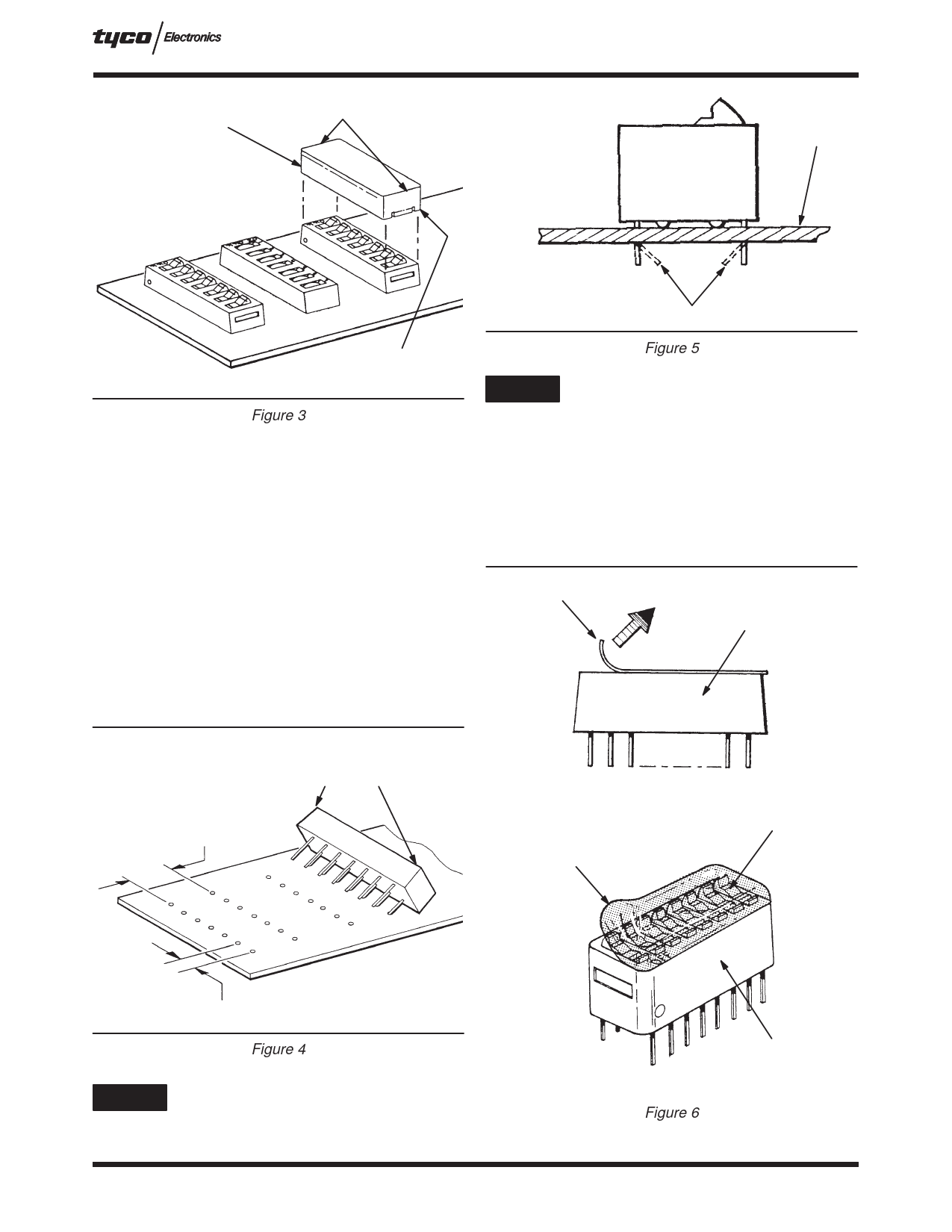
Protective Cover
DIP Switches (7000 and 7100 Series)
Grip Here
Housing Bottomed
on PC Board
408-7779
PC Board
Cover Latch
Figure 3
NOTE
Clinched Contact Lead (Inward Only)
Figure 5
For pc board soldering and cleaning procedures,
and recommended solvents, refer to Tyco
Electronics Application Specification 114-1056.
3.2. PC Board Installation
1. Make a layout on the pc board according to the
dimensions shown in Figure 4.
2. Make certain all contact leads have started entry
into holes. Grip sides of switch and push switch
into pc board until it is bottomed.
3. Hold switch at a slight angle and start one row
on contact leads into pc board holes. Do NOT
over–insert. Switch should be rotated until second
row of contact leads are aligned with opposite row
of contact holes.
4. SWITCH PROGRAMMING
After the switch has been inserted into the DIP socket
or soldered onto the pc board, proceed as follows:
1. Remove seal from the switches, see Figure 6.
Remove Tape
Seal from
End
Low-Profile Switch
Use Light Pressure
to Insert Switch
7.62 [.300] Ref
Rotate to Align Second
Row - Then Push Down
on Ends of Switch
Remove Seal from Top
Left to Bottom Right
(Diagonal Across the
Switch)
Masking Material
Seal
2.54 [.100] Ref
NOTE: These same procedures
apply to socket installation.
Figure 4
NOTE
To hold switch in place during wave soldering, the
four outside contact leads may be clinched
° inward at 45 . Refer to Figure 5.
Rev A
Standard-Profile or
Side-Actuated Switch
Figure 6
3 of 4
Share Link: 