BCR08AM-14 View Datasheet(PDF) - MITSUBISHI ELECTRIC
Part Name
Description
View to exact match
BCR08AM-14 Datasheet PDF : 2 Pages
| |||
MITSUBISHI SEMICONDUCTOR 〈TRIAC〉
BCR08AM-14
LOW POWER USE
PLANAR PASSIVATION TYPE
ELECTRICAL CHARACTERISTICS
Symbol
Parameter
Test conditions
IDRM
V TM
VFGT !
VRGT !
VRGT #
IFGT !
IRGT !
IRGT #
VGD
Rth (j-c)
Repetitive peak off-state current
On-state voltage
!
Gate trigger voltage
@
#
!
Gate trigger current
@
#
Gate non-trigger voltage
Thermal resistance
Tj=125°C, VDRM applied
Tc=25°C, ITM=1.2A, Instantaneous measurement
Tj=25°C, VD=6V, RL=6Ω, RG=330Ω
Tj=25°C, VD=6V, RL=6Ω, RG=330Ω
Tj=125°C, VD=1/2VDRM
Junction to case V3
(dv/dt)c
Critical-rate of rise of off-state
commutating voltage
V2. The critical-rate of rise of the off-state commutating voltage is shown in the table below.
V3. Case temperature is measured at the T2 terminal 1.5mm away from the molded case.
Limits
Min. Typ. Max.
—
— 1.0
—
— 2.0
—
— 2.0
—
— 2.0
—
— 2.0
—
—
5
—
—
5
—
—
5
0.1
—
—
—
—
50
V2
—
—
Unit
mA
V
V
V
V
mA
mA
mA
V
°C/ W
V/µs
Voltage
class
VDRM
(V)
14
700
(dv/dt)c
Min.
Unit
0.5
V/µs
Test conditions
1. Junction temperature
Tj=125°C
2. Rate of decay of on-state commutating
current
(di/dt)c=–0.4A/ms
3. Peak off-state voltage
VD=400V
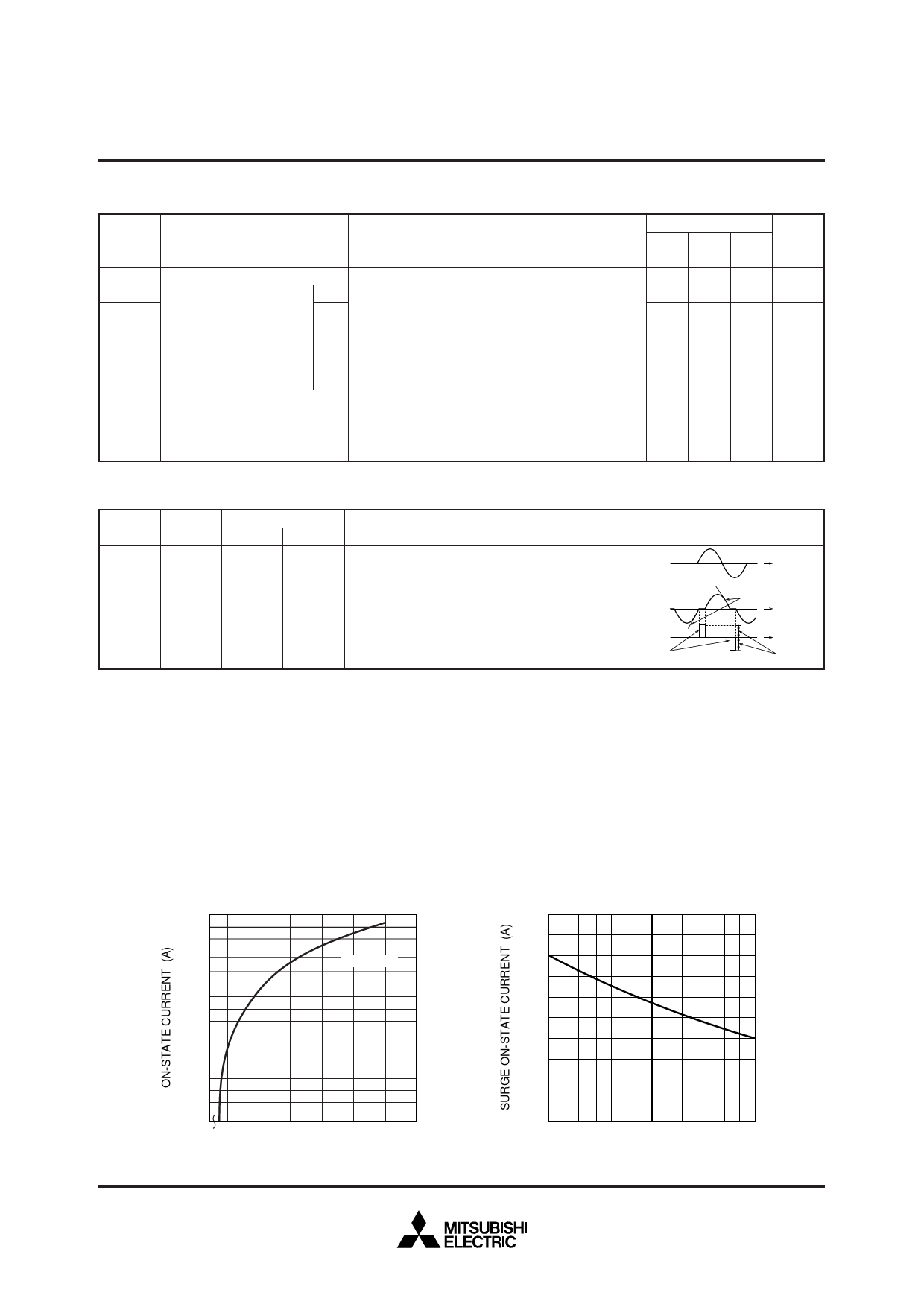
Commutating voltage and current waveforms
(inductive load)
SUPPLY
VOLTAGE
TIME
MAIN
CURRENT
MAIN
VOLTAGE
(dv/dt)c
(di/dt)c
TIME
TIME
VD
PERFORMANCE CURVES
MAXIMUM ON-STATE
CHARACTERISTICS
101
7
5
3
Tj = 25°C
2
100
7
5
3
2
10–1
7
5
3 1.5 2.0 2.5 3.0 3.5 4.0 5.0
ON-STATE VOLTAGE (V)
RATED SURGE ON-STATE
CURRENT
10
8
6
4
2
0
100 2 3 4 5 7 101 2 3 4 5 7 102
CONDUCTION TIME
(CYCLES AT 60Hz)
Feb.1999
Share Link: 