MT9T001 View Datasheet(PDF) - Micron Technology
Part Name
Description
View to exact match
MT9T001 Datasheet PDF : 37 Pages
| |||
PRELIMINARY
MT9T001
3-MEGAPIXEL DIGITAL IMAGE SENSOR
Pixel Data Format
Pixel Array Structure
The MT9T001 pixel array is configured as 2,112 col-
umns by 1,568 rows, as shown in Figure 4. Columns
from 0 through 27 and from 2,085 through 2,111, and
also rows from 0 through 15 and from 1,561 through
1,567 are optically black. These optical black columns
and rows can be used to monitor the black level. The
black row data is used internally for the automatic
black level adjustment. However, the black rows and
columns can also be read out by setting Reg0x20 (11)
and Reg0x1E (7), respectively. There are 2,057 columns
by 1,545 rows of optically active pixels, which provides
a four-pixel boundary around the QXGA (2,048 x 1,536)
image to avoid boundary effects during color interpo-
lation and correction.
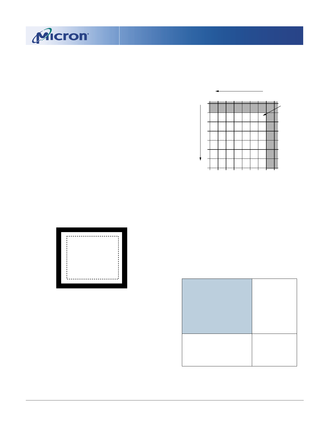
The MT9T001 uses a Bayer color pattern, as shown
in Figure 5. The even-numbered rows contain green
and red color pixels, and odd-numbered rows contain
blue and green color pixels. The even-numbered col-
umns contain green and blue color pixels; odd-num-
bered columns contain red and green color pixels.
Figure 4: Pixel Array Description
16 black rows
(0, 0)
4
27 black columns
QXGA (2,048 x 1,536)
+ 4 pixel boundary for
color correction
5 + additional active column 4
+ additional active row
= 2,057 x 1,545 active pixels
28 black columns
Figure 5: Pixel Color Pattern Detail
(Top Right Corner)
column readout direction
...
black pixels
Pixel
(28, 16)
GRGRGRG
BGBGBGB
row
readout ... G R G R G R G
direction
BGBGBGB
GRGRGRG
BGBGBGB
...
Output Data Format
The MT9T001 image data is read out in a progres-
sive scan. Valid image data is surrounded by horizontal
blanking and vertical blanking, as shown in Figure 6.
The amount of horizontal blanking and vertical blank-
ing is programmable through Reg0x05 and Reg0x06,
respectively. LINE_VALID is HIGH during the shaded
region of the figure. FRAME_VALID timing is described
in “Output Data Timing” on page 10.
Figure 6: Spatial Illustration of Image
Readout
(2111, 1567)
5
P0,0 P0,1 P0,2.....................................P0,n-1 P0,n 00 00 00 .................. 00 00 00
7 black rows
P1,0 P1,1 P1,2.....................................P1,n-1 P1,n 00 00 00 .................. 00 00 00
VALID IMAGE
HORIZONTAL
BLANKING
Pm-1,0 Pm-1,1.....................................Pm-1,n-1 Pm-1,n 00 00 00 .................. 00 00 00
Pm,0 Pm,1.....................................Pm,n-1 Pm,n 00 00 00 .................. 00 00 00
00 00 00 ..................................... 00 00 00
00 00 00 ..................................... 00 00 00
00 00 00 .................. 00 00 00
00 00 00 .................. 00 00 00
VERTICAL BLANKING
VERTICAL/HORIZONTAL
BLANKING
00 00 00 ..................................... 00 00 00
00 00 00 ..................................... 00 00 00
00 00 00 .................. 00 00 00
00 00 00 .................. 00 00 00
09005aef80c64010
MT9T001_3100_DS_2.fm - Rev. C 9/04 EN
9
Micron Technology, Inc., reserves the right to change products or specifications without notice.
©2003 Micron Technology, Inc. All rights reserved.
Share Link: 