VV5850 View Datasheet(PDF) - Vision
Part Name
Description
View to exact match
VV5850 Datasheet PDF : 41 Pages
| |||
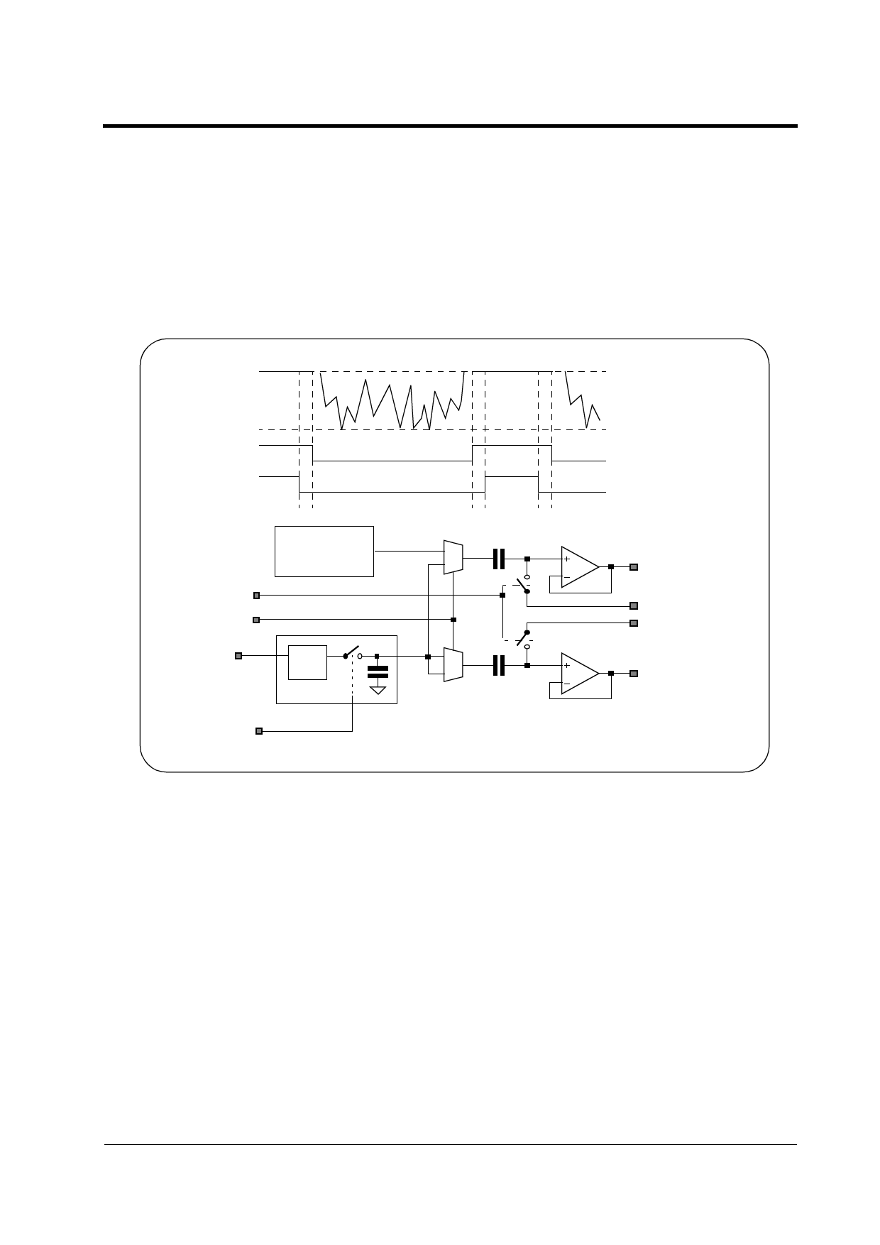
Video Output
AVO Reference
The DC content of the output stage is set by using the SELRef signal to simultaneously put the
internal reference on the AVO and AVORef output channels, and then the CLAMP signal to
charge the amplifier side of the coupling stages to VCL1 and VCL2 respectively. The integrated
5-bit DAC, controlled by Control Register bits CR[15..11], can be used to adjust one or other of
these clamping voltages. The CLAMP signal must fall before SELRef falls. The AC Coupling
Capacitors must be refreshed at least once every still image capture sequence, or every frame of
a live video.
AVO
SELRef
CLAMP
CLAMP
SELRef
Pixel Array
+ Columns
Black
rPeak
White
y
a
i n 2:1
AVO
VCL1
VCL2
VRT
SAMRef
8x8
Pixels
l i m Black Reference
AVORef
e The sensor’s internal black reference, which drives the AVORef output path, is derived from a
r separate 8 by 8 array of pixels connected in parallel. The input voltage to all pixels in the 8 by 8
P array is VRT, that is the pixels are in reset. A sample & hold stage controlled by SAMRef allows
the VRT voltage driving the black reference pixels to be sampled, freezing the black reference
value.
Normally the black level reference should be updated between every still image capture sequence
or between every frame in live video mode. Under very high illumination, however, the black refer-
ence should be sampled between every line in live video mode.
The internal black reference can be sampled at the beginning of a frame using SAMRef. It can
also be observed line by line by asserting SELRef (without CLAMP) in the dead period between
reading rows of pixels out onto AVO.
16/06/97
9
Share Link: 