74ALS646 View Datasheet(PDF) - Philips Electronics
Part Name
Description
View to exact match
74ALS646 Datasheet PDF : 13 Pages
| |||
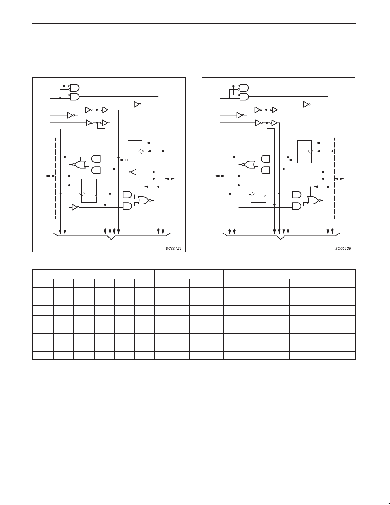
Philips Semiconductors
Transceiver/register
LOGIC SYMBOL – 74ALS646/646-1
21
OE
3
DIR
23
CPBA
SBA 22
CPAB 1
2
SAB
1 OF 8 CHANNELS
1D
C1
4
A0
1D
C1
Product specification
74ALS646/74ALS646-1
74ALS648/74ALS648-1
20
B0
LOGIC SYMBOL – 74ALS648/648-1
21
OE
3
DIR
23
CPBA
SBA 22
CPAB 1
2
SAB
1 OF 8 CHANNELS
1D
C1
4
A0
1D
C1
20
B0
VCC = Pin 24
GND = Pin 12
TO 7 OTHER CHANNELS
SC00124
VCC = Pin 24
GND = Pin 12
TO 7 OTHER CHANNELS
SC00125
FUNCTION TABLE
INPUTS
DATA I/O
OPERATING MODE
OE DIR CPAB CPBA SAB SBA
An
Bn
74ALS646/74ALS646-1 74ALS648/74ALS648-1
X
X
↑
X
X
X
Input
Unspecified* Store A, B unspecified*
Store A, B unspecified*
X
X
X
↑
X
X Unspecified*
Input
Store B, A unspecified*
Store B, A unspecified*
H
X
↑
↑
X
X
Input
Input
Store A and B data
Store A and B data
H
X H or L H or L X
X
Input
Input
Isolation, hold storage
Isolation, hold storage
L
L
X
X
X
L
Output
Input
Real time B data to A bus Real time B data to A bus
L
L
X H or L X
H
Output
Input
Stored B data to A bus
Stored B data to A bus
L
H
X
X
L
X
Input
Output
Real time A data to B bus Real time A data to B bus
L
H H or L X
H
X
Input
Output
Stored A data to B bus
Stored A data to B bus
NOTES:
H = High voltage level
L = Low voltage level
X = Don’t care
* = The data output function may be enabled or disabled by various signals at the OE and DIR inputs. Data input functions are always
enabled, i.e., data at the bus pins will be stored on every Low-to-High transition of the clock.
↑ = Low-to-High clock transition
1991 Feb 08
5
Share Link: 