CH1787(1998) View Datasheet(PDF) - Cermetek Microelectronics
Part Name
Description
View to exact match
CH1787 Datasheet PDF : 13 Pages
| |||
Return to Command State ;
The modem can be forced to reenter the command state after
dialing (without hanging up) by ending the dial command with a
semicolon. This is useful when using the modem as an auto
dialer.
Example: Touch-tone dial 9, pause, dial number, return for
command.
Enter: AT DT9, 1234567;
Result: OK
The Serial Interface Lines
The module supports a full RS-232C/V.24 serial interface. Signal
levels are TTL rather than RS-232C level compatible, which al-
lows you to directly connect the modem to your hosts UART with-
out level translating circuitry. A complete description of each signal
follows under Pin Description.
Two of these lines are all that are required for proper modem
operation: TXD, RXD and DTR. The modem is controlled by send-
ing it serial commands over TXD and can be monitored by serial
status messages returned on RXD.
Automatic Answering
The S0 register controls the number of rings that must occur
before the modem answers a call. The register may range in
value from 0-255
All other serial interface lines may be utilized for the convenience
of your application but are not required by the modem. Unused
outputs (from modem) should be left unconnected. Unused in-
puts should be tied to the proper logic level. See pin description.
S0
DO NOT ANSWER TELEPHONE
S1
ANSWER ON RING 1
S2
ANSWER ON RING 2
S3
ANSWER ON RING 3
S0=255 ANSWER ON RING 255
When S0 is set to 0, the modem will not auto-answer.
Example: Assign the value 6 to S0 to set the modem to answer
on the sixth ring.
Enter: AT S0=6
Result: OK
DIAL A NUMBER D
The Dial command takes the form Dn, where n is a string of char-
acters. In the simplest form, n will be only the digits of the phone
number to be dialed.
Example: Dial number.
Enter: AT D1234567
In response to this command, the modem dials the telephone
number 123-4567 and then waits for carrier from a distant mo-
dem. If no carrier is detected within a given time (the default time
is 30 seconds), the modem automatically releases the line and
sends a NO CARRIER result code. If carrier is detected, the mo-
dem gives a CONNECT result code and goes on-line, permitting
communication with the distant modem.
The Dial Command may also be issued without a telephone num-
ber. ATD causes the modem to pick up the telephone line without
dialing a number.
CONNECTING TO THE HOST UART
Since a modem communicates data serially and most host prod-
ucts handle data in a parallel format, a UART is needed to make
parallel-to-serial and serial-to-parallel translations.
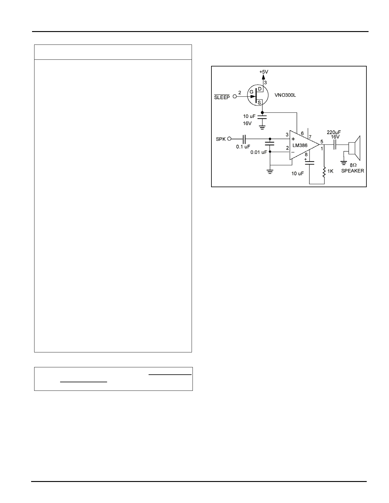
Figure 5. Speaker Control Circuit--optional to allow for call
progress monitoring.
Phone Line Connection Guidelines
1) The mounting of the CH1787 in the final assembly must be
made so that it is isolated from exposure to any hazardous
voltages within the assembly. Adequate separation and re-
straint of cables and cords must be provided.
2) The circuitry from the CH1787 to the telephone line interface
must be provided in wiring that carries no other circuitry than
that specifically allowed in the rules (such as A and A1 leads).
3) Connection to phone line should be made through an RJ-11
jack.
4) Traces from the modems RING and TIP pins to the RJ-11
jack must exceed 0.1 inch spacing to one another and 0.2
inch spacing to all other traces. The traces should have a
nominal width of 0.020 inches or greater.
5) The RING and TIP traces should be as short as possible and
oriented to prevent coupling other high speed or high frequency
signals onto the host circuit card.
6) No additional circuitry other than that shown in the following
Figure may be connected between the modem module and
the RJ-11 jack.
7) The CH1787, the RJ-11 jack, the interfacing circuitry and traces
in between, must be mounted on a circuit board with a 94 V-0
flammability rating.
Cermetek Microelectronics, Inc.
Document No. 603-0182 Rev. D (11/98) 8
Share Link: 