L74VHC1GT09 View Datasheet(PDF) - Leshan Radio Company,Ltd
Part Name
Description
View to exact match
L74VHC1GT09
Leshan Radio Company,Ltd

L74VHC1GT09 Datasheet PDF : 6 Pages
| |||
LESHAN RADIO COMPANY, LTD.
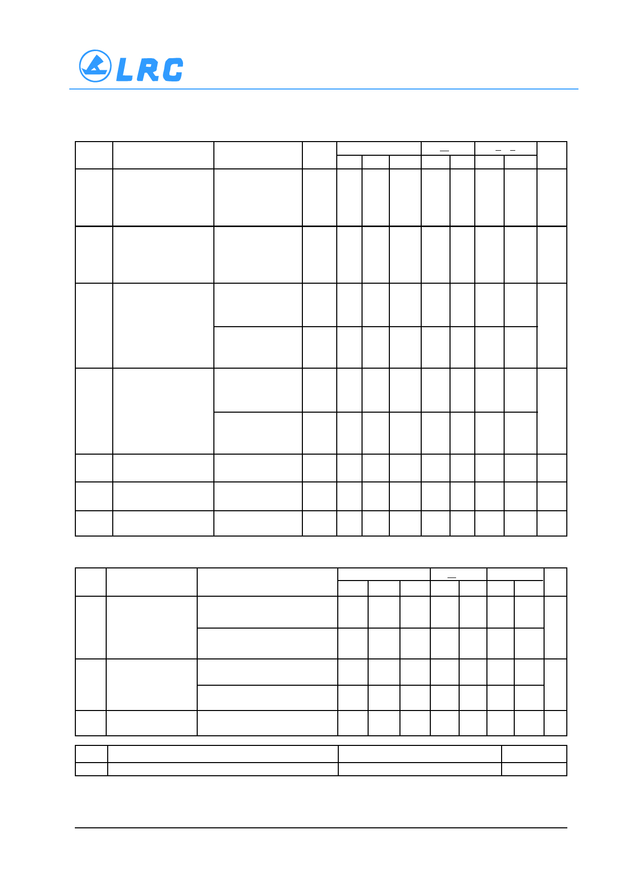
DC ELECTRICAL CHARACTERISTICS
Symbol
V IH
Parameter
Minimum High–Level
Input Voltage
Test Conditions
V IL
Maximum Low–Level
Input Voltage
V OH Minimum High–Level
Output Voltage
V IN = V IH or V IL
V OL Maximum Low–Level
Output Voltage
V IN = V IH or V IL
I IN
I CC
I OPD
Maximum Input
Leakage Current
Maximum Quiescent
Supply Current
Maximum Off–state
Leakage Current
V IN = V IH or V IL
I OH = – 50 µA
V IN = V IH or V IL
I OH = –4 mA
I OH = –8 mA
V IN = V IH or V IL
I OL = 50 µA
V IN = V IH or V IL
I OL = 4 mA
I OL = 8 mA
V IN = 5.5 V or GND
V IN = V CC or GND
V OUT = 5.5 V
L74VHC1GT09
V CC
T A = 25°C
T A < 85°C –55°C<TA<125°C
(V) Min Typ Max Min Max Min Max Unit
V
3.0 1.4
1.4
1.4
4.5 2.0
2.0
2.0
5.5 2.0
2.0
2.0
V
3.0
0.53
0.53
0.53
4.5
0.8
0.8
0.8
5.5
0.8
0.8
0.8
2.0 1.9 2.0
1.9
1.9
V
3.0 2.9 3.0
2.9
2.9
4.5 4.4 4.0
4.4
4.4
3.0 2.58
2.48
2.34
4.5 3.94
3.80
3.66
2.0
0.0 0.1
0.1
0.1 V
3.0
0.0 0.1
0.1
0.1
4.5
0.0 0.1
0.1
0.1
3.0
4.5
0 to5.5
0.36
0.44
0.52
0.36
0.44
0.52
±0.1
±1.0
±1.0 µA
5.5
2.0
20
40 µA
0
0.25
2.5
5.0 µA
AC ELECTRICAL CHARACTERISTICS C load = 50 pF, Input t r = t f = 3.0 ns
Symbol Parameter
t PZL Maximum Output
Enable Time,
Input A or B to Y
t PLZ Maximum Output
Disable Time
C IN Maximum Input
Capacitance
Test Conditions
V CC = 3.3 ± 0.3 V C L = 15 pF
R L = R I = 500 Ω C L = 50 pF
V CC = 5.0 ± 0.5 V C L = 15 pF
R L = R I = 500 Ω C L = 50 pF
V CC = 3.3 ± 0.3 V C L = 50 pF
R L = R I = 500 Ω
V CC = 5.0 ± 0.5 V C L = 50 pF
R L = R I = 500 Ω
T A = 25°C
T A < 85°C –55°C to 125°C
Min Typ Max Min Max Min Max Unit
6.2 8.8
10.5
12.5 ns
8.7 12.3
14.0
16.5
4.3 5.9
5.8 7.9
8.7 12.3
7.0
9.0
9.0
11.0
14.0
16.5 ns
5.8 7.9
9.0
11.0
6.0
10
10
10 pF
C PD
Power Dissipation Capacitance (Note 6)
Typical @ 25°C, V CC = 5.0 V
18
pF
6. C PD is defined as the value of the internal equivalent capacitance which is calculated from the operating current consumption without
x x . load. Average operating current can be obtained by the equation: I CC(OPR) = C PD V CC f in + I CC C PD is used to determine the no–
x x x load dynamic power consumption; P D = C PD V CC 2 f in + I CC V CC .
3/6
Share Link: